The last post detailed the new 32 way connector pin out and the reasons it was necessary to update the old design. In order to be able to use the new pin out you first need a new motherboard:

Reflecting the new 7HP (35mm) module width, this motherboard has twelve slots instead of the previous six. With this many slots, it is possible to consider building a complete mixer in a 19 inch rack width. With twelve slots you can have eight input channels and still have four slots left for bus amps.
Talking of bus amps, our old friend the Twin Line Amp (TLA) has been update to a 35mm module width:

Notice the three tubes of the original TLA have been mounted vertically so they will fit into a 35mm wide module. Unfortunately there is no room for the pair of input transformers the original TLA had. With a bit of PCB layout tweaking it might just be possible to squeeze in one small diameter mic transformer like the Cinemag CMMI-10PCA which is just under 28mm in diameter but that is for the future. For the present we have a half sized pair of bus amps.
Buses need channels to feed them and channels need mic pres. The Classic mic pre was the test bed for trying out vertical tube mounting so it was a natural to convert to the new pin out:

It also sports a new front panel layout and some extra features. First the four toggles have been rearranged into a square so save space. Secondly a stepped gain control has been added to make it operate more like a conventional mic pre is expected to work. Lastly a simple 12dB/octave HPF has been added.
This module is also the first to benefit from the new module mechanical design. From the left the module looks just like a PCB:

But there is a hint of something going on to the right:

And looking at the module from the right makes it clear the steel screen of the new mechanical design is being used. The steel screen is attached at the front using the same small die castings that are used to fix the front panel to the PCB and at the rear it is mounted to the top of the 32 way connector using a couple of pillars. This makes for a very strong, rigid box construction. You can see how the box is formed in this top view:

You can see the pillars used to connect the steel screen to the 32 way connector and the small die castings used to connect it to the front panel.This picture also illustrates the new front panel controls mounting scheme discussed in an earlier post. Here is a close up of the front of the module from above:

To the right is the front panel, at the top is the steel screen, the main Classic PCB is at the bottom and you can see the two small die castings coupling the front panel to the steel screen and the main PCB. Just behind these die castings is a small new PCB which is parallel to the plane of the front panel. It is attached to the front panel solely by the toggle switches and the rotary switch controls fitted to the front panel. This one has four Molex connectors mounted on its rear surface. Two are for mic and line inputs, one is the output to the mic input transformer and the third is both input and output to the HPF and the stepped gain control. The PCB is just 26mm wide and 100mm tall. If you want to change the controls on the front panel all you have to do is create a new version of this small PCB. In the old scheme, where controls were fitted to the main PCB, you would have had to create a complete new main PCB 100mm by 160mm to achieve the same result. The new scheme makes customising modules a lot simpler and cheaper.
Talking of making things cheaper, the new module mechanics cost a fraction of the cost of the Fischer modules I used to use but there are still some expensive items in it. The worst culprit is the small die casting of which four are used. Right now these cost over £4 each if you buy them from Farnell. They are still more then £2 if you buy 25 of them. Other distributors, such as Digikey, have them at lower prices, where they are just over £1. Even at this price, they contribute over £4 to the price of the enclosure. However, thanks to a groupDIY member, there is an even cheaper alternative. It is a small brass cube made by Ettinger:

Secondly, the fixing points on the front panel are different. They are slightly closer to the edge which actually makes a little more space available on the front panel. They are also smaller than the die castings which reduces the amount of front panel area they consume which also helps with front panel layouts.
Lastly, the spacing between the front panel and the main PCB is slightly less using the Ettinger cubes. It is not much, about 0.2mm or 8 mil, but it will mean the 32 way connector will mate 8 mil less with the motherboard connector. I do not expect this to be a problem but I will move the holes on the PCB to compensate for this in the next PCB revision.
The new front panel controls mounting scheme has also been used in the creation of the first 35mm EQ module. This EQ is based on my REDD EQ design which had fixed frequency high and low controls and selectable frequencies for mid boost/cut. The new design extends this by adding three selectable high frequencies and three selectable low frequencies. I call it the REDDPLUS:

It is a relatively simple EQ. In line with the general thinking of trying to reduce costs, some design decisions have been made which at once simplify the design but also add features. The major simplification is to remove the requirement for cut Q to be the same as the boost Q. This makes the EQ a bit more like the Helios 69 EQ where the cut Q is sharper than the boost. This makes sense since cutting tends to need to be more surgical than boosting. This means we no longer need a 2 pole 12 way switch for the mid section. Instead we can use a much cheaper single pole 12 way switch and we only need one inductor for the mid band instead of two. The second simplification is to remove the requirement for the Q to be the same at each frequency setting (constant Q) and instead use constant bandwidth. This significantly simplifies the frequency selection switching to the point where we can select three frequencies with a single toggle switch. These same concepts have been applied to the Low and High bands to extend them to operate at three different frequencies. The resulting front panel looks like this:
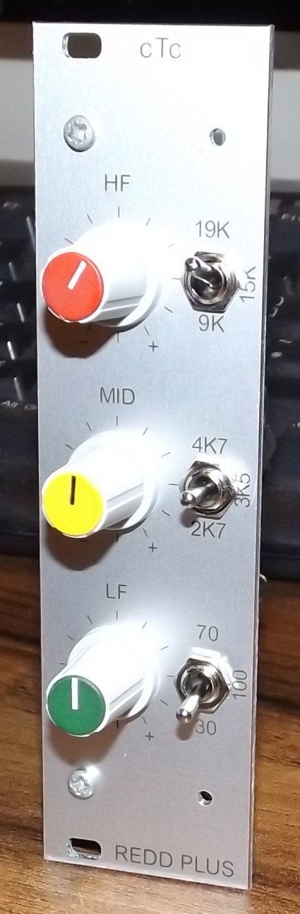
There are just three 11 way rotary switches that provide up to10dB boost/cut in 2 dB steps and three toggles switches each of which selects one of three frequencies. The next version will include an EQ in/out switch as well.
I mentioned earlier there is not enough room on the TLA board for an input transformer. However, if you build it on a 6U high PCB there is plenty of room. There is also room for an output transformer and room enough for a line input transformer that can be used as the return from a balanced insert. Not only that, there is also room to fit the above mentioned REDDPLUS EQ which together would make a complete 35mm channel amplifier. There will be more details of this in a future post because I have only just sent off the PCB layout for prototypes to be made. In the meantime here is a picture of the PCB layout:

And a first draught of a front panel layout:
