Friday 28 March 2014

Prototype Profile

The Schroff extrusions and side plates arrived this morning about a week after I placed the order. Well done ForeMost Electronics for thrashing the 2 to 3 weeks estimated delivery.  I spent the afternoon sketching possible mixer profiles. I know I want a 9U main sloping panel at an angle of around 35 degrees. I know I need 4U horizontally in front of this for the fader nose and it needs to be deep enough to leave room at the back for a 3U space for bus amplifiers and the like. Apart from that, the overall shape can be anything I fancy. I also know the fader nose has to be about 200mm high so that the main 9U space can sit at 35 degrees. If it is anything less than this then the slope rapidly increases and we end up with a profile like the 500 pictured in the previous post.

The piece of wood I have is 1800mm by 450mm so the biggest profile I could do would be 900mm deep and 450mm high. I did a profile in wood some time ago using wood that was only 340mm high and 800mm deep. I laid out the Schroff end plates on this to see if they could be made to fit. As the piece of wood is only 340mm high the 9U space ends up at a rather shallow angle but the profile looks quite promising:


The 4U fader nose is on the right. This is a standard Schroff 4U paenl which is 175mm deep. As you can see, the bottom corner of the sloping 9U section is very close to the bottom of the wood. I laid a Eurocard PCB with the 32 way connector in the bottom part of this 9U space and you can see that by the time the mating half of the connector and the motherboard have been added there would be no room to run the cables from the fader nose to the motherboard. There is room at the rear (bottom left) for a 3U section for the bus amps etc. and possibly room for another at the top or at least a 3U high space to fit all the connectors. There is not really any more space in this profile than there is in the Rackz enclosure I am using for the EZTubeMixer demo and that one is far too cramped for easy wiring assembly. So, although this profile is possible. it does have some drawbacks.

I then realised that 9U is a fraction over 400mm and the new piece of wood I have is 450mm high. This means it would be possible to fit a 9U side plate at the rear of the mixer. The bottom 3U could be used for bus amps etc. and the top 6U could be divided into two more 3U spaces for input and output connectors. Furthermore, this 9U could be placed so there was a 25mm gap below and above it. Those two 25mm spaces could be used to fit wooden bottom and top pieces. The fader nose would now be 25mm higher making it a total of 200mm which is what we need for the 35 degree slope. So I drew this out on paper several times and concluded that it would still fit nicely into a depth of 800mm. Although the wood I have could make a 900mm deep profile I felt this was too close to the 1000mm width of the mixer. 800mm would make it look more rectangular. Here is the result:


The slightly greater angle means there is now plenty of room for the wiring from the fader nose and there is a lot more room between the main 9U sloping space and the rear mounted bus amps which should make wiring a lot easier. There is also plenty of space on the rear for connectors. The flat top towards the rear is just over 300mm deep - just big enough to lay a near field monitor on top.

The next step is to fix the side plates to the wood and attach the extrusions to make the basic framework of the mixer.

Thursday 20 March 2014

The Big Picture

All the tube mixers I have built so far have been  based on Eurocard 19 inch sub-racks housed in off the shelf enclosures. The first one was housed in a standard 6U high 19 inch rack cabinet and the EZTube Mixer demo unit is being built into a sloping 19 inch rack case made by Rackz. The advantage of using off the shelf enclosures is that, as they are made in quantity, they are relatively cheap; the Rackz enclosure for instance is only £150. The disadvantages of using them are:
  • They are usually made from steel as it is cheaper and stronger than aluminium of the same thickness. Unfortunately this makes them rather heavy. It also means they are good magnetic conductors and this can cause problems with coupling magnetic fields from power supply transformers into sensitive microphone transformers.
  • They are only available in standard sizes. This is fine as long you can fit the mixer you need into that size but more often that not you cannot.
  • There never seems to to be enough room for all those little extras. For example, right now I am trying to find room for the eight output transformers in the EZTube Mixer demo mixer. Originally I thought they would fit on the base of the Rackz enclosure towards the rear. Now I have wired up all the mic and line inputs and the channel faders, this space is now clogged with cables. Now I need to find somewhere else to put them.

The bottom line is that off the shelf enclosures are suitable only for a limited number of applications. For anything with more than six channels and a few monitoring facilities, an off the shelf enclosure will not do. What  we need is a simple way of constructing mixers of any size and shape we desire.

The EZTube Mixer modules fit into a standard 19 inch sub-rack as do the new 6U modules described in the previous post. The sub-rack has a very simple method of construction. It consists of little more than a pair of end plates with holes in and aluminium extrusions holding them together. My first idea was to extend this by making  end plates of different shapes. This is basically the way consoles were constructed when I was at Neve. The end plates, called cheeks at Neve, were made of one eighth inch (3mm) aluminium and were held together by extruded rails. Different width sections were made using different lengths of extrusion and sections were bolted together to make a complete console.

The first question this raises is the length of the extrusions. Standard extrusions used in 19 inch sub-racks are long enough for 6 modules. All the various manufacturers of sub-racks will make you an extrusion of any length. Some of them supply extrusions in 1 metre lengths so you can cut them to any length you want. So it looks like arranging different extrusion lengths is not a problem.

The next question is the shape and the position of the holes in the end plates (cheeks). Here we hit a serious problem. All the manufacturers of sub-racks and extrusions have slightly different  sizes and shapes of extrusions and corresponding slight differences in the distances between the holes that hold the extrusions. This means it is not possible to design a cheek to use anybody's extrusion so if you decide to go this route you really have to pick a manufacturer and stick with them. The prospect of being able to make a cheek in any shape you like is so tempting that it is very hard not to accept being limited to a single supplier of extrusions. And this is exactly what I did at first. I decided to use a local supplier, a company called SRS, who have so far given me excellent customer service. I decided initially on a section width of 8 modules, ordered some custom exrusions from SRS and began designing cheek profiles.

I looked at lots of different mixer profiles from classic Neve's to modern low profile desks. I wanted room for a 6U channel module and a 3U one either above or below it and also a 'nose' to house standard 100mm throw faders. I also thought it would be a good idea to have some rear facing 3U modules for additional Twin Line Amps, output transformers and connectors. The modules need about 220mm of depth to allow room for the motherboard and the wiring beneath it. This means if the front panel slope is shallow, the fader nose turns out quite deep. If it is too shallow there is not enough height the fit the rear facing modules. This sets a lower limit to the slope of the front panel. As you increase the angle, the fader nose becomes less deep and you soon have enough height to fit the rear facing modules. An angle of around 45 degrees seemed to work well and is similar to the angle used in some early Neve consoles. The result is shown below:


The large white oblongs are cut outs to allow wiring to pass from one section to another. This is quite a large piece of metal and is over 700mm deep. After talking to Frank Rollen, who would make the cheeks for me, it became clear that cheeks that could fit into a 500mm square of 3mm aluminium sheet would be the most cost effective. As a result of this I designed what I called the 500 cheek.

At first this went well.  There are only a limited number of ways you can fit a 6U and a 3U module into a 500mm square and I took inspiration from some early Helios consoles and set the front slope at around 60 degrees. At this angle, and with a 150mm nose for the faders, there was just enough room to include a 3U bridge above the sloping section but unfortunately no room for any rear facing modules. However, there was room for a small scribble strip between the bottom module and the fader nose.The 500 cheek looks like this:


In creating these cheek drawings I learnt a lot. First I needed a way to import non-standard shapes into Front Panel Designer so I could add the holes and send them complete cheek design to Frank. Front Panel Designer will accept non-standard shapes in the form of a .dxf 2D CAD file. Fortunately I discovered LibreCad which is a free 2D mechanical CAD program that is relatively easy to use. I could then draw the shape of a cheek and import it into Front Panel Designer. Next you need to know where to put all the holes to attach the extrusions. To do that you need detailed drawings from manufacturers. These are easy to obtain and are all in .dxf format so could use LibreCAD to read them.  Next I had to extract the positions of the holes from these drawings. This proved more difficult than expected. For reasons best known to themselves, mechanical designers dimension their drawings in rather obscure ways which means you have to add and subtract several figures to get the one you need. It is easy to make errors in this process. Once you have all the figures you need you then have to add the holes to the cheek drawing. This turns out to be considerably complicated by the fact that the front panel is sloping which involved lots of trigonometry to work out the x,y coordinates of each hole. Fortunately Front Panel Designer allows you to rotate a group of holes, so I created 3U, 6U and 9U macros of the holes needed and simply rotated them in Front Panel Designer.

Having gone to all this effort I got Frank to make me a couple of the 500 cheeks and I assembled them with the 8 module long extrusions provided by SRS. The first build looked like this:


Unfortunately, when I tried to fit the faders I discovered I had forgotten to allow for the thickness of the extrusions in working out the depth of the fader nose so the space for the faders was a few mm too short. However, I managed to drill new fixing holes for the rear fader extrusion about 10mm further back which then left enough room for the faders to fit in. This meant I also had to move up  by 10mm the extrusion that held the bottom of the scribble strip which is OK as it just made the scribble strip space a little smaller. There is now a small gap between the rear fader extrusion and the bottom scribble strip extrusion. I plan to fill this with a red leather strip attached to a piece of dowelling and thus a blunder becomes a cosmetic detail!. Here is a picture of the 500 cheek fitted with the new 6U channel modules and eight faders:


So far so good but an awful lot of effort went into creating the 500 cheeks and despite taking a lot of care over it I still made mistakes. The whole process would need to be repeated for a different cheek profile and to be honest, I really do not look forward to lots of mechanical CAD work so although this method clearly works and can produce nice looking results I really wanted to find an easier method.

For some time I had been corresponding with Pierre Petit and Holger Classen, both of whom were building their own EZTube Mixers. Holger had completed one in a 19 inch rack unit and Pierre was still building his. Pierre's approach was interesting because he made his cheeks from wood and simply screwed standard sub-rack end panels to them and then connected them together with standard extrusions. There's no need for complex CAD drawings of end cheeks and the question of cosmetic cladding is solved. Here is a link to a picture of Pierre's console:

Pierre's Console

This approach is not without its problems. One of these is that standard sub-rack wide extrusions leave a small gap at each end of the mixer front that is normally filled by the sub-rack ears. As Pierre is not using sub-rack ears, there is a small gap next to each wooden cheek. Pierre's solution to this was to find a special extrusion that would fill this gap. There is also the question of how to fit the side panels to the wood. The bolts used to fit the extrusion to the side panels are not countersunk and the side panels are probably not thick enough to be countersunk. This means you probably need to drill holes in the wooden cheeks where the extrusions bolts go so the side plates can fit flush with the wooden cheek. This is not too hard to do and at least you can use the side plate as a template.

So far this method uses standard sub-rack parts so sections of the mixer have to be 6 modules wide . You can probably add sections which gives you a wood trim every six modules rather than just one at each end of the mixer  and mixers would have to be multiples of six modules wide - Pierre's mixer has two sections of six modules each. Then Holger had a brain wave. He realised that the 1 metre long extrusions made by some sub-rack manufacturers are almost exactly 14 modules wide (there is about 4mm left over). Combine that with Pierre's idea of using standard side plates attached to wooden cheeks and you have the basis of a means of building decent sized mixers with almost any cheek profile. With a 14 module wide frame you can build one almighty tube mixer. And that is just what Holger is doing. It seems to me to be a brilliant solution. You can ring the changes in the wooden cheeks to make quite complex mixers if you choose.

My only reservation is whether the extrusions would be strong enough over a length of a metre but Holger has already checked this out with some one metre rails he got from Fischer. Here is a link to a one metre long 3U monster section:

Holger's One Metre Monster

I am convinced this is the way to go so I decided to build my own prototype one metre wide frame. I have already got the wood, some pine furniture wood, and I am busy finalising the details of the cheek profile. Then there was the question of where to get the one metre extrusions. Clearly you can get them from Fischer but in the UK you have to go through their distributor so I though I would try Schroff. They have a UK branch so I contacted them and told them what I wanted. Apart from some minimum order quantities their prices seemed quite reasonable but they insisted I work through their UK distributor which is Forward Electronics Limited. Here we go again, I thought. Another link in the chain with a profit margin to make, but I was pleasantly surprised to get a rapid response with keen prices from Forward Electronics and a delivery time of only 2 to 3 weeks. So I have placed an order with them for sufficient extrusions and side panels to make a one metre mixer with a 9U module space at the front and a 3U rear facing module space. The other handy thing about using Schroff is that they have a 4U side plate which is just perfect for housing 100mm faders.

In the meantime I will use the 500 frame as a test bed for the new 6U modules and build myself a nice 6 or 8 into 2 tube mixer.

Monday 17 March 2014

In The Beginning...

 My first all tube mixer is now in daily use in a studio in Switzerland. I learnt a lot from building it and the lessons learned were incorporated into the design of the EZTube Mixer. The improvements were mainly in the circuit design to provide better drive capability and more control over the gain, the addition or more comprehensive EQ and improvements in the mechanism for plugging in the modules. And once again, I have learnt a lot from building the EZ Tube Mixer. Some aspects of its design worked well and others less so. The purpose of the Mark 3 design is to improve upon the EZTube Mixer design to create an even better all tube mixer.

The first area that could benefit from improvement is the overall construction of the channel module. Most EZTube Mixer channel modules consist of two PCBs attached to a front panel. One PCB contains the main mic pre and gain make up amplifiers and the second usually holds a passive EQ. Routing switches and pots and some EQ pots and switches are mounted directly  onto the front panel and hand wired to the PCBs. The principal strength of this design lies in its flexibility. By simply by changing the front panel and/or the EQ PCB you can build  a wide variety of channel modules. The weak points of this design are:

1. Mechanical integrity. Each PCB is attached to the front panel by a couple of screws and the mic pre PCB interfaces to the rest of the mixer via a 32 way connector that plugs into a backplane PCB. As there are no card guides, it can be difficult to locate the 32 way connector into the back plane and when you push home the module, all the strain is taken by the PCB.

2. The flexibility means each module leads to a lot of hand wiring. This is time consuming, is prone to errors and is not particularly neat

3. The PCBs generally have an earth plane which provides some degree of screening but the overall mixer design relies a lot on the the screening provided by the sub-rack and its add-on screens for ensuring the channel modules are adequately screened. This is fine as long as you stick to off the shelf sub-racks for which add-on screens are available but as soon as you want move away from standard widths, screening becomes a problem.

4. If you need a balanced output, for an insert or direct out for instance, the output transformer has to be fitted external to the module.

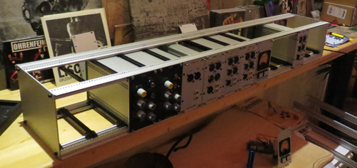
The solution to the mechanical integrity and screening weaknesses is to house the channel module in a screened box of some sort. I looked at standard sub-rack modules by several manufacturers a few years ago but abandoned the idea because of the expense of these modules. However, I was recently introduced to the range of sub-rack modules made by Fischer in Germany. Many of these use a pair of extrusions to form the sides of the box, which makes them very strong,  and front and rear panels are attached by screws that fit into tapped holes in the extrusions. They are thus much simpler to assemble than many of the modules made by other manufacturers and turn out to be substantially cheaper. Both 3U and 6U versions are available with built in ventilation grills in the top and bottom which is ideal for tube circuits. Here is a picture of one of the 6U units made by Fischer:


This version has black anodised aluminium extruded sides and a plain aluminium front panel. The extrusion includes a lip intended to engage with a card guide which will ensure the unit slides in easily and mates properly with the backplane PCB. In the 3U version the PCB is supported along its entire length so there is no danger of it bending  when it is plugged into the backplane. The complete screening this enclosure provides means you need little or no additional screening outside the module as almost all audio connections to and from the module are made by screened cables.

The next problem to attack is the large amount of hand wiring required inside a channel module. As this hand wiring provides a great deal of flexibility, any solution needs to be able to retain as much flexibility as possible without requiring lots of hand wiring. Part of the problem lies in the pads on the existing PCB that are intended to be used for interconnections within the board and between boards. For example, there are pads for the mic input, the line input, phantom power, mix buses and so on. To avoid having to wire directly to these pads, a possible improvement is to replace them all with connectors. Now, instead of soldering wires, we simply plug in some pre-made cables. This is convenient for rapid assembly or disassembly but it simply moves the problem to cable assembly. Soldering cables to connectors is no more fun than soldering them to PCBs. It would be nice not to have to solder these at all. One obvious alternative is to use IDC connectors and ribbon cable but many of the connections need to be screened so ribbon cable is not an option. A better alternative is to use crimp connectors in the same way they were used in the EZTube Mixer for screened cable connections from the back of the mother board to external connectors and other components of the mixer e.g. faders.. They also work well for small numbers of unscreened connections. So I have altered the PCB layout of the mic pre PCB to incorporate Molex KK connectors for for all these links. I have also added connectors for the outputs of the two amplifiers and for the input to the gain make up amplifier so that board to board connections can be made by plug in cables.

This solves part of the interconnect problem but not for the EQ. The three band Pultec is the worst. It has 6 pots and two switches external to the EQ PCB, a total of 27 wires to connect. Assembly would be simplified if all these additional controls could be mounted on a separate PCB and connected to the main EQ PCB.These only connect over a short distance so screened cables are not essential especially as the channel amp is now inside a completely screened enclosure. So a ribbon cable might do for this but it means relaying out all the EQ PCBs to incorporate a ribbon connector as well as laying out the PCBs for the extra controls for each EQ. Since I have three standard EQs at present, that means laying out a total of 6 PCBs. Not an impossible task but it does mean that for any new EQ it would be necessary to lay out two more PCBs. Again, flexibility involves a lot of work so I looked for ways of reducing it. I realised that all the current EQs are 3 band and they all use three Grayhill switches in more or less the same positions so it occured to me we could have a single three switch PCB wired to standard IDC headers and include the EQ itself on the PCB holding the additional controls. All current and future EQs would use the three switch PCB and an EQ  specific one. This reduced the number of PCB layouts from six to four and meant that new EQs would only need one PCB to be designed rather than two. So far so good. It then occurred to me that, if this three switch PCB was going to be used in every channel amp then we might as well incorporate it with the mic pre PCB and have a single standard 6U PCB that fitted directly into the Fischer module. This would have the further advantage that the 6U PCB would be fully supported on two edges just like the 3U ones would be.


I then spent some time laying out a prototype  6U PCB with three Grayhill switches placed below the mic pre. It turns out that this leaves a good sized area behind the switches, probably big enough to house a VTB2291 output transformer. However, I was not happy with the way a VTB2291 would be attached to the PCB and I thought it likely the mass of the transformer could damage the PCB in  when transported if secured only at two points. I then contacted Colin at Audio Mainteneance to see if there was any possibility of obtaining a VTB2291 in a PCB mounting format similar to the VTB1847. It turns out that this is no problem and Colin was able to send me a prototype to try out.  Not only is it no problem, but because it is just a slight tweak to the process of manufacturing an existing transformer, there is no price increase either.

There is also room on the PCB for an extra input transformer, so to test out all these ideas I designed a prototype 6U PCB and had a few made. Here is a picture of the prototype 6U PCB:


At the top running from left to right is the mic pre with the 32 way EZTube Mixer style connector to the far right and the phase/pad/phantom and mic/line switches plus stepped gain control on the left. In the middle from the centre to the bottom are the three Grayhill switches. The board is laid out to accept either one or two bank switches in any of the three positions and each bank is brought out to its own 26 way IDC connector. 26 ways may seem like a lot for a 12 way switch but it does mean all 12 connections can be brought out to one side of the connector which greatly simplifies the EQ PCB layout. Behind the switches, more or less dead centre, is the new output transformer with its Molex KK connector to its right and below that is the footprint for a second input transformer. You will also notice I have added a second 32 way connector below the mic pre. The reason for this is that there are not enough pins on the mic pre 32 way connector to bring out the balanced output. I have taken the opportunity to add additional buses to this connector and also an auxiliary power supply for things like LEDs and relays. These are just ideas at the moment and may well change as the design firms up.

As I mentioned at the start, PCBs in the EZTube Mixer were simply attached to the front panel by a couple of screws and the new EQ boards could be mounted in the same way but, in the interests of improving mechanical integrity, I decided not to rely on this alone. So I have added positions on the 6U PCB for four pillars to provide additional support for the EQ PCB. These are labelled P1, P2, P3 and P4. Here is a picture showing how the PCB plus pillars slides into the module:


As well as adding connectors for internal connection, I made  several other improvements to the mic pre PCB layout ,some of which were suggested by existing users (thank you Holger and Pierre).

1. The gain setting coupling capacitor and resistor positions of each amplifier have been swapped so that the resistor is connected to 0V rather than the capacitor. The main reason for doing this is that the junction of the gain setting resistor and capacitor is a virtual earth. As the resistor is now ground referenced, you can connect a large number of other resistors to this junction and use the amplifier as a virtual earth mixer (rather than the passive mixing scheme that is used at present).

2. The current design has the phase change switch before the mic/line switch. Since it is useful to be able to change the phase on line inputs as well I have moved the phase change switch to be after the mic line switch.

3. There is a pre-set trimmer resistor on the PCB to set the gain of the gain make up stage. This needs to be set to give overall unity gain when the passive EQ is in circuit. The trimmer is not conveniently placed to do this so I have moved it to the front of the PCB so it can be accessed in a fully assembled module via a small hole in the front panel. The Twin Line Amp version of this PCB might be used as a pair of gain make up amplifiers so the trimmer for the first stage (not normally used when configured as a mic pre) has also been moved forward so that it could be accessed through the front panel if the stepped gain switch were not fitted.

3. The holes at the top of the current mic pre PCB, used to hold the mic and line input cables, make the cables interfere with card guides (which can be used in 3U versions of the EZTube Mixer).These holes have been deleted.

4. The tops of the two output tubes and their bases are close to the metal parts of the module extrusions. They have therefore been moved in towards the mid line of the PCB to keep them well away from the metal extrusions.

I have yet to build one of the 6U PCBs and I am currently designing a prototype matching Helios EQ PCB to try with it.