- They are usually made from steel as it is cheaper and stronger than aluminium of the same thickness. Unfortunately this makes them rather heavy. It also means they are good magnetic conductors and this can cause problems with coupling magnetic fields from power supply transformers into sensitive microphone transformers.
- They are only available in standard sizes. This is fine as long you can fit the mixer you need into that size but more often that not you cannot.
- There never seems to to be enough room for all those little extras. For example, right now I am trying to find room for the eight output transformers in the EZTube Mixer demo mixer. Originally I thought they would fit on the base of the Rackz enclosure towards the rear. Now I have wired up all the mic and line inputs and the channel faders, this space is now clogged with cables. Now I need to find somewhere else to put them.
The bottom line is that off the shelf enclosures are suitable only for a limited number of applications. For anything with more than six channels and a few monitoring facilities, an off the shelf enclosure will not do. What we need is a simple way of constructing mixers of any size and shape we desire.
The EZTube Mixer modules fit into a standard 19 inch sub-rack as do the new 6U modules described in the previous post. The sub-rack has a very simple method of construction. It consists of little more than a pair of end plates with holes in and aluminium extrusions holding them together. My first idea was to extend this by making end plates of different shapes. This is basically the way consoles were constructed when I was at Neve. The end plates, called cheeks at Neve, were made of one eighth inch (3mm) aluminium and were held together by extruded rails. Different width sections were made using different lengths of extrusion and sections were bolted together to make a complete console.
The first question this raises is the length of the extrusions. Standard extrusions used in 19 inch sub-racks are long enough for 6 modules. All the various manufacturers of sub-racks will make you an extrusion of any length. Some of them supply extrusions in 1 metre lengths so you can cut them to any length you want. So it looks like arranging different extrusion lengths is not a problem.
The next question is the shape and the position of the holes in the end plates (cheeks). Here we hit a serious problem. All the manufacturers of sub-racks and extrusions have slightly different sizes and shapes of extrusions and corresponding slight differences in the distances between the holes that hold the extrusions. This means it is not possible to design a cheek to use anybody's extrusion so if you decide to go this route you really have to pick a manufacturer and stick with them. The prospect of being able to make a cheek in any shape you like is so tempting that it is very hard not to accept being limited to a single supplier of extrusions. And this is exactly what I did at first. I decided to use a local supplier, a company called SRS, who have so far given me excellent customer service. I decided initially on a section width of 8 modules, ordered some custom exrusions from SRS and began designing cheek profiles.
I looked at lots of different mixer profiles from classic Neve's to modern low profile desks. I wanted room for a 6U channel module and a 3U one either above or below it and also a 'nose' to house standard 100mm throw faders. I also thought it would be a good idea to have some rear facing 3U modules for additional Twin Line Amps, output transformers and connectors. The modules need about 220mm of depth to allow room for the motherboard and the wiring beneath it. This means if the front panel slope is shallow, the fader nose turns out quite deep. If it is too shallow there is not enough height the fit the rear facing modules. This sets a lower limit to the slope of the front panel. As you increase the angle, the fader nose becomes less deep and you soon have enough height to fit the rear facing modules. An angle of around 45 degrees seemed to work well and is similar to the angle used in some early Neve consoles. The result is shown below:

The large white oblongs are cut outs to allow wiring to pass from one section to another. This is quite a large piece of metal and is over 700mm deep. After talking to Frank Rollen, who would make the cheeks for me, it became clear that cheeks that could fit into a 500mm square of 3mm aluminium sheet would be the most cost effective. As a result of this I designed what I called the 500 cheek.
At first this went well. There are only a limited number of ways you can fit a 6U and a 3U module into a 500mm square and I took inspiration from some early Helios consoles and set the front slope at around 60 degrees. At this angle, and with a 150mm nose for the faders, there was just enough room to include a 3U bridge above the sloping section but unfortunately no room for any rear facing modules. However, there was room for a small scribble strip between the bottom module and the fader nose.The 500 cheek looks like this:

In creating these cheek drawings I learnt a lot. First I needed a way to import non-standard shapes into Front Panel Designer so I could add the holes and send them complete cheek design to Frank. Front Panel Designer will accept non-standard shapes in the form of a .dxf 2D CAD file. Fortunately I discovered LibreCad which is a free 2D mechanical CAD program that is relatively easy to use. I could then draw the shape of a cheek and import it into Front Panel Designer. Next you need to know where to put all the holes to attach the extrusions. To do that you need detailed drawings from manufacturers. These are easy to obtain and are all in .dxf format so could use LibreCAD to read them. Next I had to extract the positions of the holes from these drawings. This proved more difficult than expected. For reasons best known to themselves, mechanical designers dimension their drawings in rather obscure ways which means you have to add and subtract several figures to get the one you need. It is easy to make errors in this process. Once you have all the figures you need you then have to add the holes to the cheek drawing. This turns out to be considerably complicated by the fact that the front panel is sloping which involved lots of trigonometry to work out the x,y coordinates of each hole. Fortunately Front Panel Designer allows you to rotate a group of holes, so I created 3U, 6U and 9U macros of the holes needed and simply rotated them in Front Panel Designer.
Having gone to all this effort I got Frank to make me a couple of the 500 cheeks and I assembled them with the 8 module long extrusions provided by SRS. The first build looked like this:

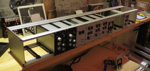
Unfortunately, when I tried to fit the faders I discovered I had forgotten to allow for the thickness of the extrusions in working out the depth of the fader nose so the space for the faders was a few mm too short. However, I managed to drill new fixing holes for the rear fader extrusion about 10mm further back which then left enough room for the faders to fit in. This meant I also had to move up by 10mm the extrusion that held the bottom of the scribble strip which is OK as it just made the scribble strip space a little smaller. There is now a small gap between the rear fader extrusion and the bottom scribble strip extrusion. I plan to fill this with a red leather strip attached to a piece of dowelling and thus a blunder becomes a cosmetic detail!. Here is a picture of the 500 cheek fitted with the new 6U channel modules and eight faders:

So far so good but an awful lot of effort went into creating the 500 cheeks and despite taking a lot of care over it I still made mistakes. The whole process would need to be repeated for a different cheek profile and to be honest, I really do not look forward to lots of mechanical CAD work so although this method clearly works and can produce nice looking results I really wanted to find an easier method.
For some time I had been corresponding with Pierre Petit and Holger Classen, both of whom were building their own EZTube Mixers. Holger had completed one in a 19 inch rack unit and Pierre was still building his. Pierre's approach was interesting because he made his cheeks from wood and simply screwed standard sub-rack end panels to them and then connected them together with standard extrusions. There's no need for complex CAD drawings of end cheeks and the question of cosmetic cladding is solved. Here is a link to a picture of Pierre's console:
Pierre's Console
This approach is not without its problems. One of these is that standard sub-rack wide extrusions leave a small gap at each end of the mixer front that is normally filled by the sub-rack ears. As Pierre is not using sub-rack ears, there is a small gap next to each wooden cheek. Pierre's solution to this was to find a special extrusion that would fill this gap. There is also the question of how to fit the side panels to the wood. The bolts used to fit the extrusion to the side panels are not countersunk and the side panels are probably not thick enough to be countersunk. This means you probably need to drill holes in the wooden cheeks where the extrusions bolts go so the side plates can fit flush with the wooden cheek. This is not too hard to do and at least you can use the side plate as a template.
So far this method uses standard sub-rack parts so sections of the mixer have to be 6 modules wide . You can probably add sections which gives you a wood trim every six modules rather than just one at each end of the mixer and mixers would have to be multiples of six modules wide - Pierre's mixer has two sections of six modules each. Then Holger had a brain wave. He realised that the 1 metre long extrusions made by some sub-rack manufacturers are almost exactly 14 modules wide (there is about 4mm left over). Combine that with Pierre's idea of using standard side plates attached to wooden cheeks and you have the basis of a means of building decent sized mixers with almost any cheek profile. With a 14 module wide frame you can build one almighty tube mixer. And that is just what Holger is doing. It seems to me to be a brilliant solution. You can ring the changes in the wooden cheeks to make quite complex mixers if you choose.
My only reservation is whether the extrusions would be strong enough over a length of a metre but Holger has already checked this out with some one metre rails he got from Fischer. Here is a link to a one metre long 3U monster section:
Holger's One Metre Monster
I am convinced this is the way to go so I decided to build my own prototype one metre wide frame. I have already got the wood, some pine furniture wood, and I am busy finalising the details of the cheek profile. Then there was the question of where to get the one metre extrusions. Clearly you can get them from Fischer but in the UK you have to go through their distributor so I though I would try Schroff. They have a UK branch so I contacted them and told them what I wanted. Apart from some minimum order quantities their prices seemed quite reasonable but they insisted I work through their UK distributor which is Forward Electronics Limited. Here we go again, I thought. Another link in the chain with a profit margin to make, but I was pleasantly surprised to get a rapid response with keen prices from Forward Electronics and a delivery time of only 2 to 3 weeks. So I have placed an order with them for sufficient extrusions and side panels to make a one metre mixer with a 9U module space at the front and a 3U rear facing module space. The other handy thing about using Schroff is that they have a 4U side plate which is just perfect for housing 100mm faders.
In the meantime I will use the 500 frame as a test bed for the new 6U modules and build myself a nice 6 or 8 into 2 tube mixer.
No comments:
Post a Comment