Saturday, 9 July 2016

6U Modules Update

The original 6U channel concept was to have a common motherboard containing uncommitted EQ switches connected to IDC connectors. Specific EQ boards would be connected to the EQ switches using ribbon cable. In this way a common motherboard could be used and a channel could be configured for any EQ simply by fitting the appropriate EQ board.

Here is a picture of the prototype 6U motherboard:


To the left is the mic pre and at the bottom right you can see the EQ switches and their associated IDC headers (two per switch). You can also see, above the switches, a space for fitting an output transformer. This means a module can be completely self contained with transformer balanced inputs and outputs. Unfortunately there are no spare pins on the standard 32 way EZTubeMixer connector for a balanced output so, rather than change the original 32 way pin out,  I have added a second 32 way connector. This will have the same basic pin out as the original but allocated differently. The mic and line balanced inputs can be used as inputs or as outputs. For example, you could have a balanced output from the mic pre which feeds an insert connected to the extra connector mic input pins. The balanced return would be fed to the extra connector balanced line input. You can see on the right hand side of the PCB where I have made provision for an extra input transformer for just this purpose. This would allow you to have a pre-EQ balanced insert or to use the mic pre and EQ independently.

After basic assembly, the PCB looks like this:
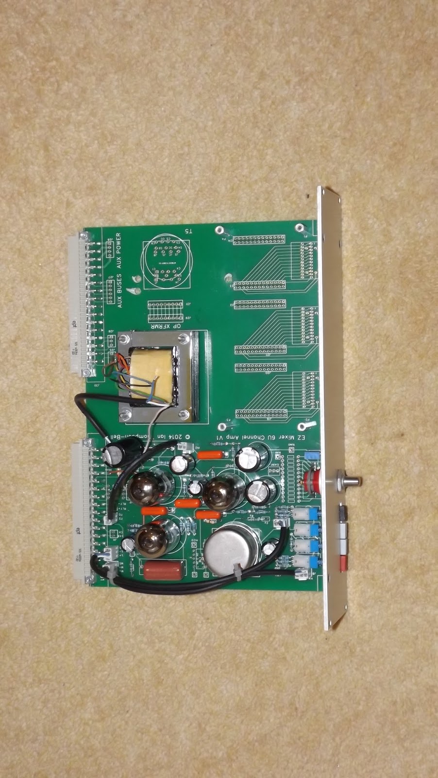


The uncommitted EQ switch and IDC headers idea is fine in theory but it did not work out in practice. The capacitance of the ribbon cable seriously upset the operation of the EQ, especially on the high frequency ranges and they also consume a lot of space on the EQ daughter-board. I wanted to retain the mother/daughter board flexibility, so I looked at simplifying the wiring between the two.

At that stage, the prototype 6U PCB had provision for three switches. Each one is tracked for two banks and up to 2 poles per back. Each bank is tracked to its own 26way IDC connector which means there is a total of six connectors.

The first EQ I worked on was the Helios 69 EQ daughter board. As the bass switch uses 2 banks it needs a pair of 26 way connections. These connectors take up a lot of room on the PCB, more than the switch would have done. There are only 26 connections required (two lots of 12 plus two commons) so a single 26 way connector would be sufficient. The only reason to have two 26 way connectors is if a four pole 6 way switch is required.

I therefore decided to review the switches used in the current range of EQs to see if it would be possible to use just a single 26 way connector per switch. The table below shows the switches used in the current EQs.

EQ
LO
MID
HI
OTHER
3B PULTEC
2P6W
1P12W
1P6W

HELIOS 69
2P12W
1P12W
1P12W

REDD
2P12W
2P12W
1P12W
2P6W


It is clear that no more than two poles are required. In the 2P12W cases, the poles are on different banks but for the 2P6W case both poles are on the same bank. So, although we never need more than 2 poles, they can come from four possible places.

However, we never use both poles on the second bank, in fact we only ever use the first pole on the second bank when we use a 2P12W switch. This means we can forget the second pole in the second bank. Also, whatever switch we use, we always use the first pole on the first switch so this can be permanently tracked to the 26 way connector. Now all we are left with is selecting between the second pole on the first bank in the 2P6W. We can do this with a set of three pads and a link.

The 26 pins of the connector have been allocated as follows:


CONN PIN
SW PIN
CONN PIN
SW PIN
1
Bank 2 Pin1
2
Bank 1 Pin 1
3
Bank 2 Pin 2
4
Bank 1 Pin 2
5
Bank 2 Pin 3
6
Bank 1 Pin 3
7
Bank 2 Pin 4
8
Bank 1 Pin 4
9
Bank 2 Pin 5
10
Bank 1 Pin 5
11
Bank 2 Pin 6
12
Bank 1 Pin 6
13
Bank 2 Pin 7
14
Bank 1 Pin 7
15
Bank 2 Pin 8
16
Bank 1 Pin 8
17
Bank 2 Pin 9
18
Bank 1 Pin 9
19
Bank 2 Pin 10
20
Bank 1 Pin 10
21
Bank 2 Pin 11
22
Bank 1 Pin 11
23
Bank 2 Pin12
24
Bank 1 Pin 12
25
Bank 2 Com
26
Bank 1  Com


This scheme reduces the the number of connectors by half and would hopefully not affect the performance of the EQ. Here is a picture of the updated 6U PCB:


Des[ite all these efforts,  the EQ performance was still compromised. So this scheme has been abandoned. Instead, each EQ type will have its own unique channel PCB. This means more PCBs have to be designed but it does mean the EQ will work as advertised. The first of these PCBs looks like this:


The mic pre section is unchanged but the EQ section now includes an almost complete Helios 69 style EQ. The only parts not on the PCB are the two pots, the peak/trough switch and the EQ in/out switches.. These will be connected to a very simple daughter board via a ribbon cable.

In parallel with this I have been developing the twin line channel (TLC) PCBs. These are intended to form the basis of a  line in line out mixer with two AUX sends and a pan pot per channel with two channels to a module Again a mother board daughter board concept is used but there are far fewer connections between mother and daughter board then in the case of the standard channel module.The first of these developed was the REDD EQ. The reason is that these EQ sections can be cut and pasted between Channel and TLC mother boards so I only have to lay out each EQ once. Here is a picture of the prototype REDD EQ TLC:


The top of the PCB is essentially a standard Twin Line Amp (TLA). At the top left of the PCB are three pots; these are the two AUX sends and the pan pot. Below them is the channel mute switch. Below the mute switch are two preset pots that are used to set  the gain of each half of the TLA so it can make up the loss in the EQ. These are arranged so as to be accessible through small holes in the front panel to simplify set up.

Below these is the EQ itself. It is a new version of the REDD EQ with all for switches in line. The top one is the 10KHz shelving EQ, the two middle ones are the mid boost/cut and mid frequency select switches and the bottom one is the 100Hz shelving EQ. The only component not on the PCB is the EQ in/out switch. If required this can be fitted directly to the front panel and wired to pads provided. It can be fitted in between the 10KHz switch and the gain trim pots.

Above and below the EQ are four holes labelled P1, P2, P3 and P4. These are for the pillars on which will be mounted the second identical EQ.  SImilarly, there are two holes above and below the AUX and pan pots on which will be mounted the AUX send, pan pot and channel mute controls of the second channel. The daughter EQ connects to the second input transformer and the second gain make up amp of the TLA section

The EQ has already been commissioned and it works well. The next stage is to check out the AUX send and pan pots then develop the two mother board PCBs.

Friday, 19 December 2014

6U Modules Part 1


The MKIII uses 6U high channel modules built using extruded aluminium 'cassettes' made by Fischer Electronik. First we need to sort out all the basic mechanical details of the cassettes and the key dimensions for determining the position of controls on the front panel. Later sections cover specific modules.

In general there are two distinct types of channel modules. First there is the regular channel amp based on the EZTubeMixer channel amplifier with its four push buttons and stepped gain control. Each one has an EQ section and an optional routing section. The second type is the twin line input channel. These have no mic pre controls but contain two identical line input channels each with a three band EQ and an optional routing section.

Basics

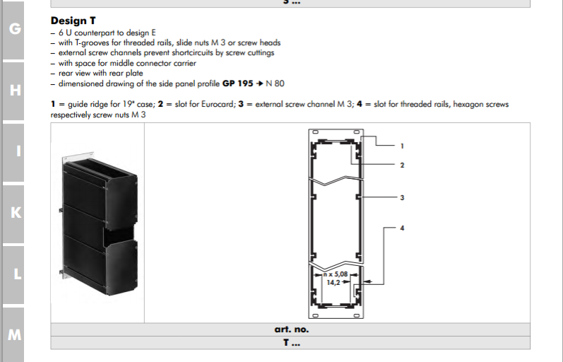
The Mark III 6U modules are based on an extruded aluminium cassette made by Fischer Elektronik in Germany. They have several types of 6U cassette but we need one that has a cut-out at the rear so it can be used with 3U backplane PCBs that have a centre support. The preferred type is therefore the Fischer model T:

Fischer6UTmodulebrochure.png

Note: this drawing shows that the top surface of the PCB is 14.2 mm from the left hand side of the front panel. This sets the position of all the controls mounted on the main 6U PCB and is crucial in calculating the x-position of holes on the front panel.

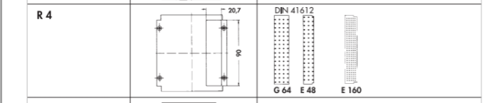
There are several rear panel options. Mostly we just need the type with a single connector hole at the top:

FischerR4rearpanel.png


All the modules are 14HP (2.8 inches wide). I have obtained a drawing of the Fischer standard dimensions for this size of front panel:


Fischer6U14HPfrontpaneldwg.png


The overall panel width is 70.9mm. The overall panel height is 261.8mm. The front panel fixing holes are 3.4mm diameter, countersunk and are set in 5mm from the edges.

A standard 6U PCB is 233.4mm tall. We assume the PCB is centred on the front panel. This means the bottom of the PCB is 14.2mm from the bottom of the front panel. This is crucial for calculating the y-position of holes on the front panel.

Mic Pre Channel Amplifier

The MK III mic pre channel amplifier is based on a standard 6U motherboard. This houses standard EZTubeMixer mic pre and gain make up amplifiers with the usual push buttons for phantom power, 20dB pad, mic/line selection and phase change and the standard 12 way Grayhill switch for gain setting. The Grayhill datasheet shows that the centre of the shaft of this switch is 9.35mm above the PCB surface and since the PCB surface s 14.2mm from the left hand side of the front panel, the switch shaft is:

14.2 + 9.35 = 23.55mm from the left hand edge of the front panel

The datasheet for the push buttons shows that the centre of their shafts is 5mm above the PCB surface or 19.2mm from the left hand edge of the front panel. The push buttons will take 6mm diameter round push on knobs so the hole diameter for these should be 6.5mm. The table below shows the y-coordinate of the push buttons and the gain switch on the PCB in mil, the equivalent y-coordinate of the holes for them on the front panel in mm and the corresponding x-coordinate in mm.


Control
PCB y-coord ( mil)
Panel y-coord (mm)
Panel x-coord (mm)
Phantom
8401
227.59
19.2
Pad
8007
217.59
19.2
Mic/Line
7614
207.59
19.2
Phase
7220
197.59
19.2
Gain
6433
177.6
23.55

In addition, provision is made for up to three two deck 12 way Grayhill switches for EQ use. Each switch is wired directly to a 26 way IDC connector. The centres of the shafts of the three switches are set at exactly 1.0, 2.6 and 4.2 inches respectively from the bottom of the PCB. In other words they are 1.6 inches apart starting 1 inch from the bottom of the PCB.. Since the bottom of the PCB is 14.2mm from the bottom of the front panel we can calculate the front panel positions of each switch:


Switch
x - position mm
y -position mm
1
23.55
39.6
2
23.55
80.24
3
23.55
120.88

Depending on the shaft size of the switches, the front panel hole diameter needs to be either  0.25 inches (6.35mm) for the one eighth inch diameter shaft and 0.375 inches (9.6mm) for the one quarter inch diameter shaft.

The EQ itself is housed on a daughter board mounted above the motherboard on pillars and connected to the EQ switches using ribbon cables. Ideally we would like the controls on this PCB to be the same distance from the right hand side of the front panel as the motherboard switches are from the left hand side i.e.

70.9 -23.55 = 47.35mm from the left hand side

Most of the controls on the daughter board will be EQ pots and my preferred type is made by OMEG. The shafts of these pots are 12.5mm from the surface of the PCB. Since the PCB is 1.6mm thick, to get the pot shafts in the right position the pillars need to be:

47.35 -12.5 -1.6 -14.2 = 19.05mm tall.

This is just enough to clear the switches but makes no allowance for the legs of components on the daughter board. In addition 19mm pillars are non-standard so I have decided to use 20mm pillars. This means the EQ pots are 1mm closer to the right hand side of the front panel. This means the x-position of the pot shafts on the front panel is:

14.2 + 20 +1.6 + 12.5 = 48.3mm

The daughter boards is supported by four pillars. The bottom pair are 0.252 inches from the bottom of the PCB. The motherboard fits into slots in the enclosure extrusions so the daughter PCB has to be a little smaller so as not to foul the enclosure. So, the bottom pillars on the daughter board are 0.160 inches from the bottom. If we want the the EQ pots on the daughter board to line up with the EQ switches on the motherboard then the pots need to be:

0.252 - 0.160 = 0.092 inches lower down the PCB

so the PCB y- positions of the pots are:  0.908, 2.508 and 4.108 inches respectively.

There is room between these pots for additional controls where required. To summarise, the front panel positions of the pots are:


Pot
x - position mm
y -position mm
1
48.3
39.6
2
48.3
80.24
3
48.3
120.88

Lastly, there is a pre-set potentiometer used to set the EQ gain make up that needs to be accessible through a small hole in the front panel. The screw of the pot is 7.9mm above the PCB so its x-coordinate is 14.2 + 7.9 = 22.1mm.  The centre of the pads of the pot is 5777 mil from the bottom of the PCB. However, the screw is 50 mil below this so the screw is 5727 mil from the bottom of the PCB. Its front panel y-coordinate is therefore:

5.272 * 25.4 + 14.2 = 148.11mm

The hole size needs to be large enough to accommodate a small screwdriver about 3.2mm in diameter so we will make this hole 4mm diameter.

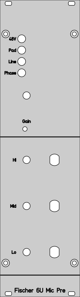
The front panel layout below shows the the basic layout of the controls discussed above:

6UFischermicprereference.png


Specific EQs will be described in subsequent posts.

Monday, 20 October 2014

Virtual Earth Mixing and Alternative Output Transformers

I mentioned in the previous post that the gain setting resistors of the channel amplifiers have been zero referenced making virtual earth mixing a possibility. I have now received prototype PCBs of the V2 Twin Line Amplifier (TLA) which incorporates the relevant improvements added to the channel amplifiers:
  • Provision for Molex KK connectors for internal wiring
  • Amplifier gain preset pots moved to be accessible from the front panel
  • Tubes moved so as not to foul the enclosure
  • Ground reference the gain setting resistors so each amplifier can be used as a virtual earth mixer

In addition, a couple of other improvements have been made:
  • Inclusion of a series 1N4007 in the HT+ line to protect against accidental reversal of the HT supply
  • Addition of a 100nF capacitor across the HT supply where it enters the PCB to prevent the instability that can occur when several modules are connected.
  • Moved one output capacitor so as not to be directly above a 6922 which makes it too hot.

The new TLA V2 is shown below:


Apart from the modifications listed above, the new TLA is functionally identical to the original TLA and can be used wherever the original was used. The one thing this TLA can do that the original cannot is virtual earth mixing and this is what I wanted to test out. I used my new test rack (shown below) to feed the output of the new channel amplifier to one of the buses via a 47K resistor and connected one of the new TLA virtual earth inputs to the same bus. I measured the output of the the channel amplifier and also the output of the TLA virtual earth amplifier. They were within 0.2dB of each other. Allowing for tolerances in the two output transformers included in the test circuit, this is a good result, implying the virtual earth mixer gain is very close to unity as expected, However, when I measured the noise, the result was rather disappointing at only -63dBu; clearly not good enough for any serious mixer. I checked the output of the channel amp in case this was the source of the noise but this was much lower so the noise clearly was introduced by the TLA. I then realised I had forgotten to connect the +ve input of the TLA (the one used for passive mixing) to 0V. I added the necessary link and the noise dropped below -80dBu.

This means virtual earth (VE) mixing is now a potential alternative to the normal passive mixing I use in my mixers. The reason I use the word 'potential' is that VE mixing has it own set of problems, the most serious of which is instability caused by bus capacitance. This is particularly problematic where op amps are used. They have a fixed open loop gain but the closed loop noise gain depends on the number of sources feeding the VE. This means the amount of negative feedback (NFB) varies which affects stability. Steve Dove, in his excellent series on mixing console design goes into more detail about this problem. To paraphrase Steve:

"Bus capacitances, from all the cabling and PCB tracks between the channel amplifiers and the virtual earth amplifier, appears across the input of the virtual earth amplifier. This has the effect of eroding the phase margin and can lead to instability and even oscillation. This capacitance reacts against the feedback impedance to to increase the closed loop gain at high frequencies. Even a few pF is enough to tilt up the closed loop response well within the open loop parameters, threatening instability. In a real mixer with cables from many channels, hundreds of pF may be present. This makes ensuring the required phase and response characteristics very difficult. Sometimes a small series limiting resistor can be added to to define just how much this unwanted gain can rise, but this is at the expense of the ‘virtual earth’ now being determined by this resistor (which rather defeats the object)."

There is another solution to this problem and that is to vary the open loop gain as the number of channels varies. Regular op amps do not do this but many years ago a discrete op amp was designed that does exactly this. It is called a Trans Amp (note that the term Trans Amp is also used to refer to other topologies so this can be a bit confusing when conducting an on-line search). The basic idea is that the resistor that sets the closed loop gain also sets the open loop gain. If this is done correctly then the difference between the open loop gain and the closed loop gain (which is the amount of NFB applied) is practically constant which means the stability criteria are the same no matter what the gain.

This is exactly what the EZ Tube mic pre does and for similar reasons. In the mic pre, we want to be able to vary the gain over a wide range ( in this case from 6dB to 40dB) whilst maintaining stability. The EZ Tube mic pre achieves this by gradually shorting out the cathode resistor of the first tube stage of the mic pre. This gradually increases the gain of the first stage as the resistor is reduced and also gradually increases the closed loop gain. The net effect is the NFB is nearly constant and stability is assured. The TLA uses exactly the same amplifier so it also automatically adjusts its open loop gain as its closed loop gain is varied so it should make a stable VE amplifier that is insensitive to the number of channels feeding it. Note that varying the open loop and closed loop gain by gradually shorting out the first stage cathode resistor is not a new idea. The first instance I know of its use is in the V76 amplifier.

Why are we even thinking of using VE mixing when passive mixing already works very well. There are several reasons:

  • Improved crosstalk.
  • Reduced requirement for low source impedance bus drive.
  • No need to ensure unselected bus signals are connected to 0V.
  • No need to adjust the mix amp gain depending on the number of channels
The only disadvantage is that you cannot easily include a mix group fader directly across the bus before the mix amp as you can with passive mixing. This means the mix group fader has to come after the the VE amp. As this cannot drive an output directly you need another amplifier to buffer the fader and drive an output transformer. The only alternative would be to have a transformer directly after the VE amp and use a 600 ohm balanced attenuator at the output as the mix group fader.

On balance, VE mixing has a lot to recommend it so I plan to incorporate it into the 8 tracker build,

Which brings us rather neatly onto the topic of output transformers and their ability to drive 600 ohm loads. One of the most expensive items in the EZTubeMixer design is the input and output transformers so I have been looking for lower cost alternatives. Edcor is well known for its low cost transformers so I got a couple of their XSM 2.4K/600 transformers (listed at $12.97 compared to the £25 for the Carnhill VTB2291). The XSM 2.4K/600 is physically smaller than the VTB2291 normally use in the EZTube Mixer but it is rated at 2.5 watts which is well over what we need. The primary inductance measures 28H at 100Hz and the secondary is 9.8H at 100Hz, both satisfactory values. I have given this transformer a thorough test and I am pleased to report it performs almost identically to the VTB2291. In both cases, the EZTube output amplifier runs out of steam before the transformers do so I am happy to recommend this as a cheaper alternative. At +26dBu into 600 ohms the distortion with the Edcor was 0,49% and at +29dBu it became 1.1%. These results are identical to the performance of the VTB2291. Frequency response was -1.8dB at 20Hz but this is entirely due to the 4.7uF output capacitor which is 3dB down at 14Hz with the reflected secondary load.

To facilitate testing of new 6U and 3U modules and PCBs I have built a sub-rack based test rig.


On the left is space for two 6U modules and the top right row can accommodate four 3U modules. Underneath the top 3U section I have tacked a couple of input/output panels. One panel connects directly to bottom connector of  the left most 6U module to which its on board output transformer is wired. At the moment the right hand panel connects to the right most 3U module on the top row. As 3U moduels have no room for an output transformer I have mounted an Edcor one to the sub-rack behind the panel.