Monday, 4 November 2019

Transformers Review

Just about all tube audio designs need to use input and output transformers. And ones of sufficient quality are usually expensive. In addition, good quality output transformers tend to be so big they will not fit inside a tube mixer module.

So, as part of the drive to reduce the cost of the Mark 3 mixer I have looked at alternative transformers to replace the relatively expensive Sowter, Jensen and Cinemag types used currently. There are three types of transformer we need; 10K:10K line input; 1:10 mic input and 2K4:600 output. A UK transformer manufacturer, OEP, makes a good range of modestly priced transformers

10K:10K Line Input

There are three OEP 10K:10K products we could use:

Z21807C    (£15 from Canford, 50% Nickel core))
A187A13C    (£25 from RS, 80% Nickel core)
K30A06C    (£40 from RS, 80% Nickel core)

All are considerably cheaper than the typical Sowter 10K:10K which is around £75. The price of each OEP alternative is directly related to its core size. Normally, level handling capability, especially at low frequencies, is directly related to core size but it does also depend on core material.

The distortion, at a range of frequencies from 1KHz down to 20Hz ,was measured for each transformer. The input signal level used was +18dBu supplied by a Lindos MS10 Audio Test Set. The transformer output was loaded with 10K in the form of a Scarlett 2i2 line input which was connected the REW software for making measurements. The results of the percentage distortion created by each transformer versus frequency are given in the table below:


Frequency
Z21807C
A187A13C
K30A06C
1KHz
0.0053
0.003
0.0024
400Hz
0.011
0.003
0.0018
100Hz
0.071
0.011
0.0018
80Hz
0.10
0.019
0.0016
63Hz
0.16
0.041
0.0023
50Hz
0.25
0.11
0.0037
40Hz
0.49
0.63
0.0063
30Hz
1.3
8.69
0.011
25Hz
5.46
17.6
0.017
20Hz
16.3
29
0.029


The performance of the Z21807C is remarkable for such a small cored transformer. Its distortion is below 0.1% down to 100Hz and quite acceptable down to 30Hz. It is only below 30Hz that its +18dBu performance falters.

The performance of the  larger core A187A13C by contrast is rather disappointing. Although distortion is very low down to 50Hz, below that frequency it rises rapidly and soon overtakes that of the smaller Z21807C.

The performance of the large cored K30A06C is exceptionally good with very low distortion at +18dBu right down to 20Hz. I conducted some additional test on this transformer  down to 10Hz where the distortion finally rose to 0.53%

The question is, under what circumstances is it really necessary to be able to cope with +18dBu signals below 40Hz? The lowest note on a bass guitar or orchestra instrument is 41.2 Hz. Some synths can reach lower but how often will such signals reach +18dBu?

Clearly in cost sensitive applications the Z21807C should be considered. If best quality is required then the K30A06C should be used and it will still achieve a good cost reduction.


2K4:600

There is no obvious OEP product for this job in their published catalogue. However, they sent me a sample of their K30A11C which is a 2K4:600 type. I tested this at +16dBu into a 600 ohm load. I also tested the Sowter 1461 which is the current preferred output transformer, at the same time. The signal source was again the Lindos test set but to reach +16dBu at the secondary requires at least +22dBu at the primary which is beyond the capability of the Lindos. So the Lindos was fed into one channel of a Twin Line Amplifier which is quite capable of outputting +30dBu into a 2K4  load and it is also what will normally be driving these transformers. The output signal was again fed via a Scarlett 2i2 into REW. For reference, the very large Carnhill VTB2291 used in the EzTubeMixer project was also tested at the same level.

The results of the percentage distortion created by each transformer versus frequency are given in the table below.

At frequencies above 50Hz the Sowter has lower distortion than the OEP but both are very low. The Sowter has typically 6dB less distortion than the OEP. Below 50Hz the Sowter distortion rises more rapidly than the OEP and at 40Hz equals the OEP. Below 40Hz the Sowter distortion rises more rapidly than the OEP and is 15.7% at 20Hz compared with 4%  for the OEP.

At mid band frequencies there is little to choose between the two but below 40Hz the OEP is definitely the better choice.


Frequency
OEP K30A11C
Sowter 1461
Carnhill VTB2291
1000
0.007
0.0053
0.031
400
0.013
0.0042
0.036
200
0.026
0.0076
0.035
100
0.054
0.019
0.033
80
0.070
0.026
0.024
63
0.095
0.041
0.023
50
0.14
0.085
0.027
40
0.22
0.21
0.035
32
0.46
0.93
0.05
25
1.36
4.74
0.084
20
4.16
15.7
0.16

The VTB2291 results are very interesting. You can see the difference in using an all steel core. Mid band distortion is much higher than the Sowter or OEP even though  the VTB2291 core is huge in comparison. But the benefit at low frequencies is clear with distortion at 20Hz. being 28dB below the OEP and nearly 40dB below the Sowter

For completeness the Carnhill VTB2291 transformer was tested down to 10Hz at +16dBm and also tested down to 20Hz at +22dBm. The results are shown below:


Frequency
Distortion @+16dBm
Distortion @+22dBm
1000
0.031
0.046
400
0.036
0.046
200
0.035
0.043
100
0.033
0.044
80
0.024
0.042
63
0.023
0.042
50
0.027
0.050
40
0.035
0.086
31
0.05
0.22
25
0.084
0.85
20
0.16
2.61
16
0.37

12.5
1.3

10
4.19


Clearly there is a trade off between performance and core type. Steel cores give higher mid band distortion but much better low frequency performance. On the other hand, cores containing nickel have much lower mid band distortion at the expense of much higher low frequency distortion. The Carnhill performance should be the standard by which alternatives are judged. With this in mind I tested two more transformers, the Carnhill VTB4096 (a high level input transformer similar to the Neve 31267) and the Cinemag 2820 which is a nickel/steel cored transformer but smaller than the VTB2291. Their measured percentage distortion at +16dBm into 600 ohms, with the VTB2291 figures included as a comparison are shown in the table below:

 
Frequency
VTB4096
Cinemag 2820
VTB2291
1000
0.0075
0.011
0.031
400
0.0054
0.010
0.036
200
0.0074
0.0098
0.035
100
0.029
0.011
0.033
80
0.055
0.013
0.024
63
0.16
0.018
0.023
50
7.1
0.026
0.027
40

0.041
0.035
31

0.076
0.05
25

0.16
0.084
20

0.39
0.16
16

1.34
0.37
12.5

4.51
1.3
10

11.0
4.19


The VTB4096 is clearly not usable. The Cinemag  transformer has a 50% Nickel core which probably explains why its mid band distortion performance is about 10dB better than the Carnhill VTB2291. However, from 40Hz downwards the differences disappear and the Carhill has lower distortion. However, the Cinemag CM2028 20Hz distortion at 0.39% is far superior to either the OEP  K30A11C (4.15%) or the Sowter 1461 (15.7%). Unfortunately this transformer is still too large to fit in a 35mm wide Mark 3 module but it might be a useful option if external transformers can be used.

1:10 mic input

The A187A15C is one of OEP’s mic input transformer products. They offer several different turns ratios but the A187A15C is a 1:10 ratio type so it is comparable with the Sowter, Jensen and Cinemag types used at present. It was initially tested at an input level of -20dBu as this represents a typical maximum mic input level (with a 20dB pad engaged the input could handle 0dBu). However, it soon became clear that this transformer can handle much higher input levels so it was tested at  -10dBu, -5dBu and 0dBu. The results are shown in the table below.

It is quite clear that at -20dBu the performance is exceptional with 20Hz distortion only 0.2% and even at 10Hz it is below 1%. At higher level the distortion increases but even at -5dBu the distortion at 20Hz is below 1%.


Frequency
-20dBu
-10dBu
-5dBu
0dBu
1000
0.0032
0.015
0.026
0.049
400
0.0021
0.012
0.021
0.038
200
0.0043
0.011
0.018
0.033
100
0.0049
0.024
0.040
0.069
80
0.014
0.038
0.063
0.11
63
0.021
0.061
0.1
0.16
50
0.032
0.098
0.16
0.23
40
0.051
0.16
0.26
0.33
32
0.081
0.26
0.39
0.47
25
0.13
0.4
0.55
0.81
20
0.2
0.6
0.76
4.17
16
0.35
0.87
1.12

12.5
0.55
1.2
2.45

10
0.87
1.69


Conclusions

Considering that most OEP transformers are half the price of their Sowter equivalents they turn in a very creditable performance. In some instances, especially at low frequencies and high levels, their performance exceeds the Sowter equivalents. At mid frequencies the Sowters undoubtedly perform better but the distortion levels in all the transformers tested are very low at these frequencies.

Considering that a typical channel strip would contain three transformers, using OEP types could reduce the BOM cost by over £100, so they should at least be offered as an alternative.

Both the Sowter and OEP output transformers perform badly at low frequencies and high levels in comparison to an all steel core transformer like the Carnhill VTB2291 which means we still do not have a top quality output transformer that can be contained inside a 35mm wide module. It is perhaps worth considering sourcing a smaller all steel core transformer just for the output stage.


Saturday, 24 November 2018

Serendipity

I think it it really wonderful when several disparate threads come together and provide inspiration as happened to me recently. The first thread was a request for four channels of tube mic pre-amplification. We initially discussed four tube mic pres in a rack mountable enclosure but it soon became apparent that what was required was a true mixer, with EQ, pan pots, rotary faders with big knobs and a monitor section. I sent the prospective customer pictures of various tube mixers from which he selected this one as being closest to what he had in mind.


It uses the old EZTubeMixer modules and rotary faders with big round knobs. And this was the start of the second thread. I had built this mixer several years previously and used a ready made steel enclosure made by a company called Rackz. So I searched the web for Rackz hoping to buy another enclosure. Unfortunately I discovered Rackz had gone bust a few days previously and their web site was no more which was a bit of a blow because they made some really nice fully screened enclosures. An extensive web search revealed absolutely nobody making anything similar so it was back to square one.

This got me thinking about another recent enquiry, this time for a rack mounted mixer, but in this instance, the prospective customer already had a custom built 19 inch rack mounting enclosure made of wood. All he needed was a rack mounting tube mixer to go in it. So I thought, why not get someone to build a wooden version of the Rackz enclosure? Fortunately there are quite a few people who make custom wood enclosures for 19 inch racks. I chose to try out Sound Desks if for no other reason than they are are in the UK and they already make something not too far away from what I need (sounddesks.co.uk).

So I drew up a very rough sketch of what I needed and sent it to them:

There is a 10U sloping spacing split into a 4U space that will contain the faders at the bottom and a 6U space above that for the channel amplifiers. At a steeper angle above that is a 3U space for the meters. At the back there is a 6U space which should be plenty for all the connectors. All in all very similar to the Rackz box. Sound Desks responded quickly with a quote which I passed on to the prospective customer who was quite happy with it.

My only concern was that the wood provides absolutely zero screening so you have to make sure the the sub-rack is fully screened, Fortunately this is not really a problem because most sub-rack manufacturers supply them for use in harsh EMC environments (like electric trains) and provide kits that allow the entire sub rack to be screened.

And this is where the third thread came in. Back in the mid 70s when I was at Neve, I once had a meeting with the man himself, Rupert Neve. When I joined Neve, Rupert had already left. The company had run into financial difficulties and to save it Rupert had sold it. The new owners kept Rupert on as a consultant but the result was he was rarely at Neve itself. When I met Rupert he had come to see my boss Tony Cornwell and after they had talked for a few minutes Tony invited me into the meeting. Rupert had brought in his his latest design for a compact radio console (known as the CRC). It was a radical departure from normal Neve build practice. The complex metal channel module enclosures were gone; modules were little more than a plug in PCB with an attached front panel. Screening between modules was to be done by steel sheets that slid in on card guides between modules. The aim was to make a Neve that was affordable by local radio stations.

I have no idea what became of the CRC as I left Neve shortly after but I never forgot the idea of a compact console which is when the three threads coalesced and I realised I had the basis of a low cost compact tube recording console. It would use:

  • Standard sub-racks with full screening which, being made in quantity are reasonably priced.
  • A wooden enclosure similar to the Rackz proving a sloping space containing slider faders and channel modules and a meter bridge that could also house 3U modules like the Twin Line Amp (for use as bus amps etc) as well as meters
  • Be populated by modified versions of the MarkIII 35mm wide modules which meant here would be space for 12 modules instead of just the six of the EZTubeMixer
For the channel module I started with the REDDPLUS channel amp. I needed to find space for a couple of Aux send controls with pre/post fader selection, a pan control and a mute, solo and pfl switches all of which are normally in the routing module in the standard Mark III layout.. The only space I could make available involved deleting the HPF (we can use the EQ instead) and the insert switch which is a bit of a luxury anyway ( there is still a per channel insert but it is unbalanced, again to simplify the mixer and keep costs down). But this space was not enough so I decided to have one Aux permanently post fade (for FX) and just the second one switchable pre/post fader (for foldback or FX). But there was still no room for this switch so the pre/post switch becomes global and Aux 2 of all channels is relay switched by a switch on the Aux master module. Even then there was not enough space so I ditched solo but kept PFL (so you can gain stage and check quality) and combined it with Mute on a single switch because you never need both at the same time. Putting the two Aux send pots side by side completed the transformation and it does fit in the space availabel (see below).

For the groups you have to have a compressor available but it would be nice to have it available when tracking. So there is a compressor for each of the Left and Right buses. They can be linked for stereo, they can be switched in and out. But they can also be disconnected from the bus and routed to TRS sockets at the rear so they can be patched into any channel using the Patch switch.

There are 8 channels and two buses which leaves two channels for Aux and monitoring. The Aux master module has master level pots for Aux 1 and Aux2 as well as the Aux 2 global pre/post switch. There is plenty of room left on this panel so I added a couple of Aux returns with individual level and Pan controls.

The final module is the monitor one. No serious mixer is complete without talkback so I included that in this module. There is a simple talkback level control and a switch to route it to the master L/R buses (slate) or to Aux 2 (foldback). When talkback is operated, the monitors are dimmed to prevent feedback and the Dim indicator lights.

Below the talkback section is the monitor section. This has a simple three position selector switch. In the centre it connects the monitor to the master L/R buses. To the right it monitors a 2 track playback input and to the left it monitors the two Aux sends outputs. The level send to the monitor amps/speakers is set by the monitor level control. PFL overrides any monitor setting and feeds the PFL bus output to both L and R monitor outputs (pre the level control). The meters are connected direct to the monitor outs pre the monitor level control so they show actual levels.

The basic layout of the mixer is shown below:


Below the channel amps  are the full throw faders and above them is the meter bridge. As shown, two meters are fitted which leaves space on either side for a pair of Twin Line Amp modules which act mainy as bus amps.

As shown, the mixer is 8 into 2 but if the Aux master, talkback and monitor functions were moved to the meter bridge it would be possible to add two more channels making it a 10 into 2. Including the two Aux returns there would be 12 inputs at mixdown.

Monday, 1 October 2018

You've Been Framed

As anyone who has read this blog will know, I am not mechanically gifted; you might even say I am mechanically dyslexic. If there are five different was to put a 19 inch enclosure together I will try all the wrong ones before finally hitting on the right one even though I have read the instructions. Fortunately I have not passed this gene on to my children. My son is the flat pack king. He can assemble any Ikea product in less than 30 minutes without the instructions.

So when it came to the frame of the Mark III tube mixer I decided to give the detail design and fabrication job to the professionals. I get all my sub-rack components from SRS here in the UK, not simply because I like to support local industry, but because they are a management buyout keen to build their business and they realise a successful business is built upon happy customers. So I sketched out what I wanted; a 30 degree sloping panel with a 3U space at the top (mostly for metering and ancillaries), a 6U space (for channel amplifiers) and a 3U space (for routing). Below this would be a horizontal 4U space for the faders. At the back would be a 9U space split into three 3U spaces. The top two are for the connections to the mixer and the bottom 3U space is for additional line amplifiers (Twin Line Amps).

The construction of the frame is really simple. It consists of a pair of side plates connected together by a bunch of standard length extrusions. The extrusions are placed in such a way as to provide the spaces required for the modules and to provide mountings for the back plane PCBs that the modules plug into.

From the users point of view the basic layout looks like this:


Because the new modules are 7HP wide (~35mm) you can fit exactly 12 of them into a standard 19 inch sub-rack that uses standard sized extrusions. So a basic mixer section is 12 modules wide. You can certainly make an 8 into 2 mixer in this format and possibly even a 10 into 2. If you want something bigger then you bolt a couple of sections together. This will give you a 24 modules wide mixer in which something like a 16 into 4 would be viable.

The two side plates that are connected together by the extrusions look like this:

Not very exciting to look at but the guts of a mixer never are. Once this has been clad in a nice looking bit of timber it will look a lot more attractive.

The hard bit is designing the side plates. It would take me simply ages to work out exactly where all the holes need to go plus one plate needs to be a mirror image of the other so you can use countersunk screws to attach the extrusions (this is necessary so you can bolt sections together to make larger mixers). So this is the job I got SRS to do. I sent them these sketches and they responded with a fully dimensioned drawing and a very reasonable quotation. I requested a couple of minor modifications and then I ordered two pairs.

I forget how long it took SRS to make them but it was not long - maybe a couple of weeks. When they arrived they looked beautiful. Nice clean countersunk holes and very handy semi-shears on the inside to aid locating the extrusions and to prevent them rotating when you tighten up the screws. I already had all the necessary extrusions so I quickly built one section. I fitted the new back plane PCBs I had designed and started plugging in modules. All the 3U spaces worked perfectly. However, when I tried the first 6U high modules (Channel One of the previous post) it would not fit. The front panel seemed to be too tall. I tried slackening off the extrusions, pushing them apart and re-tightening but this made little difference. In the end I assumed my panel design was too tall and filed down the top and bottom of it until it fitted. To be certain, I found an old blank 6U panel make by Schroff - surely they must be the right size. To my surprise it did not fit either. It was beginning to look like it was not me after all but the SRS frame. A conversation with the supplier of the Channel One front panel and trying the Schroff 6U panel in a standard SRS sub-rack convinced me something was wrong with the frame.

So I contacted SRS and explained what I thought I had found. To their great credit they immediately suggested they send someone out to look at it. Considering I am a one man band working in a shed at the bottom of the garden I was impressed by their willingness to help. I was still unsure if I had done something silly in the assembly (knowing my reputation for building things wrongly) but when Martin from SRS visted me we went though it with a fine tooth comb and he confirmed there was definitely something wrong. He suggested he took the complete assembly back to base where it could be looked at in detail. A few days later I got a call to say they had  managed to tweak it so a 6U panel fitted properly and they sent it back to me.

When it arrived I was eager to get stuck into building the first Mark III mixer but to my disappointment the 6U panels still did not fit. Whatever adjustments they had made had been lost during transportation so this was not a viable solution. After another phone call SRS agreed to subject the drawing to a thorough check. They soon called me back to say the drawings were fine so I expected to be told there was nothing they could do. But instead they said they were going to conduct a detailed examination of the complete manufacturing process to find out what had caused the problem. This took some time; about two weeks, during which time they discovered a number of small tolerances all of which could add up to the problem I had. I do not have a complete list of what they looked at but I know it included checking the length of extrusions because small variations in this parameter could cause one of an adjacent pair of extrusions to become warped when the end plates screws are tightened. I know they also checked the concentricity of the countersunk screws they were using and also the tolerances on their manufacturing machines.. In the end they made some slight changes to the design and added an extra semi shear to ensure all the extrusions are properly placed. They even checked their entire inventory of extrusions and discarded any that were not the correct length.

SRS then made me two new sets of end plates free of charge. One set they built up and thoroughly checked. The sent me this and the second pair of side plates. Again I eagerly tried a standard 6U panel in the 6U section and to my relief and joy it fits perfectly. Now I can get down to the interesting work of building a mixer.

I want to use this blog to publicly thank SRS for their tremendous support in solving this problem for me. After all I am probably their smallest customer.

Thank you  SRS

Sunday, 15 July 2018

Channel One

The channel module is the heart of any mixer. The combination of mic pre and EQ that makes up a normal channel module is what defines the basic sound palette the mixer can provide.  So, having developed the basic 35mm wide building blocks as detailed in the previous post, it is time to put them together to make a full blown channel module.

One of the benefits of having a modular approach to the PCBs that make up a module is that you can reuse them in other modules. For the first channel amp we reuse the front panel board of the the classic mic pre module (see previous post) and the front panel PCB of the REDDPLUS EQ (see previous post). I made a couple of tweaks to both of them but they are otherwise largely unchanged. These two together fit onto a 35mm wide 6U high front panel to make up the channel module. One thing we do need that is new is a 6U main PCB for the module but even this is mostly made up of PCB layouts we already have. The main mic pre section is simply the 35mm TLA stuck on a 6U PCB with some added transformers for input and output. The bottom half of the board just uses the main REDDPLUS EQ board.


One the left you can see the TLA circuit and to its right are the input and output transformers. To the right is a footprint for an additional transformer and just below it is the REDDEQ circuit. The normal signal flow is input transformer, mic pre, passive EQ, gain make up amplifier and finally output transformer. The output transformer would usually be connected to either a direct out or insert point. One advantage of having the output transformer in the channel module is it makes if very easy to build a 6U 19 inch rack containing a bunch of tube channel amps.

As you can see there is plenty of space on the board for later additions.

The red rings around the three tubes are for testing an idea to make the module more rugged. The rings are just thick enough that they are gripped between the PCB and the steel screen and, in combination with the tube sockets pins, hold the tubes firmly in place and also buffer them from external forces such as you might find in a mobile situation. In addition, it is a real pain to have to remove all the tubes from all the modules of a mixer in order to ship it. It also requires the customer to fit all the tubes to the modules before fitting the modules into the mixer. My initial idea was to stuff the space between the tubes with bubble wrap to hold the tubes in place during shipping. All the customer would have to do is remove the bubble wrap before plugging in a module. With the red rings, the tubes are already gripped firmly so none of this is necessary. The big issue is the red rings have to withstand the bulb temperature of the tubes.

The front panel has been attached so you can see the front panel mic pre and EQ boards. If you look to the left, centre and right of the front panel you will see the low cost Ettinger blocks used to connect the front panel to the PCB. You can also see pillars attached to the two mounting holes of the 32 way connector and another pillar in the top right hand corner. These, together with the Ettinger blocks, are used to mount the module steel screening plate.


The other side of the module is screened by the 0V plane of the PCB.

 And from the front it looks like this:


Now we have a proper channel amp we can think seriously about configuring a real mixer.

Monday, 21 May 2018

Come Together

It is nearly five months since my last post but a lot has been happening, mostly in trying to bring together all the design concepts detailed in previous posts and incorporate them all in the design of a real mixer. Let's start with the basic components, the PCBs.

The last post detailed the new 32 way connector pin out and the reasons it was necessary to update the old design. In order to be able to use the new pin out you first need a new motherboard:


Reflecting the new 7HP (35mm) module width, this motherboard has twelve slots instead of the previous six. With this many slots, it is possible to consider building a complete mixer in a 19 inch rack width. With twelve slots you can have eight input channels and still have four slots left for bus amps.

Talking of bus amps, our old friend the Twin Line Amp (TLA) has been update to a 35mm module width:


Notice the three tubes of the original TLA have been mounted vertically so they will fit into a 35mm wide module. Unfortunately there is no room for the pair of input transformers the original TLA had. With a bit of PCB layout tweaking it might just be possible to squeeze in one small diameter mic transformer like the Cinemag CMMI-10PCA which is just under 28mm in diameter but that is for the future. For the present we have a half sized pair of bus amps.

Buses need channels to feed them and channels need mic pres. The Classic mic pre was the test bed for trying out vertical tube mounting so it was a natural to convert to the new pin out:


It also sports a new front panel layout and some extra features. First the four toggles have been rearranged into a square so save space. Secondly a stepped gain control has been added to make it operate more like a conventional mic pre is expected to work. Lastly a simple 12dB/octave HPF has been added.

This module is also the first to benefit from the new module mechanical design. From the left the module looks just like a PCB:


But there is a hint of something going on to the right:


And looking at the module from the right makes it clear the steel screen of the new mechanical design is being used. The steel screen is attached at the front using the same small die castings that are used to fix the front panel to the PCB and at the rear it is mounted to the top of the 32 way connector using a couple of pillars. This makes for a very strong, rigid box construction. You can see how the box is formed in this top view:


You can see the pillars used to connect the steel screen to the 32 way connector and the small die castings used to connect it to the front panel.This picture also illustrates the new front panel controls mounting scheme discussed in an earlier post. Here is a close up of the front of the module from above:


To the right is the front panel, at the top is the steel screen, the main Classic PCB is at the bottom and you can see the two small die castings coupling the front panel to the steel screen and the main PCB. Just behind these die castings is a small new PCB which is parallel to the plane of the front panel. It is attached to the front panel solely by the toggle switches and the rotary switch controls fitted to the front panel. This one has four Molex connectors mounted on its rear surface. Two are for mic and line inputs, one is the output to the mic input transformer and the third is both input and output to the HPF and the stepped gain control. The PCB is just 26mm wide and 100mm tall. If you want to change the controls on the front panel all you have to do is create a new version of this small PCB. In the old scheme, where controls were fitted to the main PCB, you would have had to create a complete new main PCB 100mm by 160mm to achieve the same result. The new scheme makes customising modules a lot simpler and cheaper.

Talking of making things cheaper, the new module mechanics cost a fraction of the cost of the Fischer modules I used to use but there are still some expensive items in it. The worst culprit is the small die casting of which four are used. Right now these cost over £4 each if you buy them from Farnell. They are still more then £2 if you buy 25 of them. Other distributors, such as Digikey, have them at lower prices, where they are just over £1. Even at this price, they contribute over £4 to the price of the enclosure. However, thanks to a groupDIY member, there is an even cheaper alternative. It is a small brass cube made by Ettinger:

These are available from Farnell for less than £0.40 each. They are not 100% compatible with the die castings but they are extremely close. The main differences are first that the tapped hole used to attach the PCB is M3 rather than the M2.5 used on the die castings. Fortunately I slightly oversized the holes in the PCB so an M3 screw will just fit through the same hole.

Secondly, the fixing points on the front panel are different. They are slightly closer to the edge which actually makes a little more space available on the front panel. They are also smaller than the die castings which reduces the amount of front panel area they consume which also helps with front panel layouts.


Lastly, the spacing between the front panel and the main PCB is slightly less using the Ettinger cubes. It is not much, about 0.2mm or 8 mil, but it will mean the 32 way connector will mate 8 mil less with the motherboard connector. I do not expect this to be a problem but I will move the holes on the PCB to compensate for this in the next PCB revision.


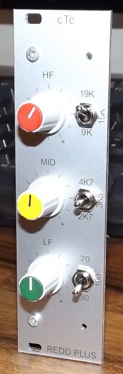
The new front panel controls mounting scheme has also been used in the creation of the first 35mm EQ module.  This EQ is based on my REDD EQ design which had fixed frequency high and low controls and selectable frequencies for mid boost/cut. The new design extends this by adding three selectable high frequencies and three selectable low frequencies. I call it the REDDPLUS:


It is a relatively simple EQ. In line with the general thinking of trying to reduce costs, some design decisions have been made which at once simplify the design but also add features. The major simplification is to remove the requirement for cut Q to be the same as the boost Q. This makes the EQ a bit more like the Helios 69 EQ where the cut Q is sharper than the boost. This makes sense since cutting tends to need to be more surgical than boosting. This means we no longer need a 2 pole 12 way switch for the mid section. Instead we can use a much cheaper single pole 12 way switch and we only need one inductor for the mid band instead of two. The second simplification is to remove the requirement for the Q to be the same at each frequency setting (constant Q) and instead use constant bandwidth. This significantly simplifies the frequency selection switching to the point where we can select three frequencies with a single toggle switch. These same concepts have been applied to the Low and High bands to extend them to operate at three different frequencies. The resulting front panel looks like this:


There are just three 11 way rotary switches that provide  up to10dB boost/cut in 2 dB steps and three toggles switches each of which selects one of three frequencies. The next version will include an EQ in/out switch as well.

I mentioned earlier there is not enough room on the TLA board for an input transformer. However, if you build it on a 6U high PCB there is plenty of room. There is also room for an output transformer and room enough  for a line input transformer that can be used as the return from a balanced insert. Not only that, there is also room to fit the above mentioned REDDPLUS EQ which together would make a complete 35mm channel amplifier. There will be more details of this in a future post because I have only just sent off the PCB layout for prototypes to be made. In the meantime here is a picture of the PCB layout:


And a first draught of a front panel layout:


Sunday, 31 December 2017

The Ins and the Outs

One of the perennial problems facing a mixer designer is how many pins to use on a module connector and what to assign to them. You could use a really large connector with many pins but this will add unnecessary cost to many smaller projects. Alternatively, you could use one standard connector and an additional one only for more complex modules. The only downside of this method is you may need two motherboards for the complex modules.

To get a better handle on the problem, let's look at the existing Eurochannel 32 way connector pin assignment.


This is the original hand drawn schematic from 2012 that defined the 32 way connector pinout. The first four pins are assigned to the mic input and the second four to the line input. Notice how the screen of each input uses two pins. The reason for this is that, at the time, I was not using a backplane PCB for the modules to plug into. Instead I was using regular connectors and wiring the backplane by hand and I found it very awkward to wire a mic cable screen to a single pin on the connector. It was much easier if I used two adjacent pins.

Next are the 48V supply and the chassis connection (which is also the 0V of the 48V). Both these use two pins each simply because they are buses and it makes hand wiring a backplane easier.

Next we have the unbalanced OUT1 and its associated 0V closely followed by the FG and FS pins. OUT1 is the output of the first amplifier in the Eurochannel design. It is often fed to an external fader and returned to the module; this is the purpose of the FS (fader slider) and FG (fader ground) pins. Not all modules or applications use this feature but it is included for those that do.

Next is a pair of pins for relay power. Most modules will need some form of auxiliary power for LEDS or relays so these two pins are often used.

Then we have four pins assigned to buses. In many cases this is too few. It allows for a stereo bus and a couple of AUX sends but this means there are none left for a solo or PFL  audio bus and its associated dc bus. We could really do with twice as many bus pins.

This if followed by the main unbalanced output OUT2 and its 0V pin.

Lastly are the power pins each of which uses two pins. The HT needs tow pins so we can ensure there is always a suitable gap between these two. The heater supply needs two pins so we can easily bus the relatively high heater current along the backplane.

As you can see, this particular pin out is determined by a variety of factors, some relevant to the module and some relevant to the process of building a mixer. It has some limitations, particularly in the number of buses and there is no provision for balanced outputs simply because in the Eurochannel design they were external.  There are also some non-optimum assignments from the point of view of PCB layout. For example, all the power supplies are at one end of the connector. From the point of view of PCB layout it would be better if they were near the middle of the connector. Despite its peculiarities, this bus standard has served well for over five years.

The new 6U modules being designed for the Mark 3 include output transformers so they need a way for these to be connected to the outside world. The 6U size board allows a second 32 way connector to be used. This can provide balanced outputs and additional buses but a lot of its pins are not really needed and this solution only works for 6U modules. It is no good for 3U modules.

Holger Classen has also been working on new versions of Eurochannel modules. His approach has been to retain the 3U module size but to make the module deeper. This allows output transformers to be fitted onto the PCB. In this way he can fit two complete mic pres into a single 3U module. He cannot add another 32 way connector so he proposed a new assignment of the existing 32 pins to allow for two balanced outputs. We have discussed this at length and made a few modifications until we were happy the new assignment would work for us both. Here is the new assignment of pins:


Notice first that the way each pin is referenced has changed. This reflects the actual row and column in which the pin is located. It also makes it clear that a three row connector is used but pins are only fitted in rows a and c. This implies a 0.2inch spacing between rows. Also, only even numbered pins are fitted which again indicates a 0.2inch pin spacing.

At the top is the first balanced input and its associated balanced output. Note that only the input has a shield. The balanced output output does not really need a shield pin (its cable screen can be connected at the XLR end) This pinout is duplicated at the bottom of the connector for the second balanced input and output. A chassis pin is located at both ends of the connector.

All the power pins are located about the centre of the connector. This time the 48V and its ground have only a single pin each, just like the utility power (which replaces the old relay power). Heaters and HT supply all have two pins each for the same reasons they did in the original. HT 0V is renamed AGND to more accurately reflect its purpose.

We now have a total of eight unassigned pins, and they are genuinely unassigned. Their purpose will be determined by the design of the backplane PCB. This provides a great deal of flexibility for both Holger and myself (Holger already makes his own backplane PCBs) but all backplane PCBs will have this core pinout. So the supplies and the chassis connections will be bused on all backplane PCBs. In 1 and In 2 will both be brought out to 3 pin Molex connectors in the same way as the mic and line inputs are at present. Out1 and Out 2 will both be brought out to 2 way Molex connectors just as Out1 and Out 2 are at present.

All other pins on the backplane PCB are assignable on a design by design basis. One new version of backplane PCB will bus pins 24a, 24c, 26a and 26c for use as mix buses. Pins 8a and 8c will be brought out to a 2 pin Molex as wil pins 10a and 10c. In many mixers these can be used for external unbalanced connections to faders or EQ. This version of back-lane PCB thus emulates the original Eurochannel backplane PCB. The designs of existing PCBs (Eurochannel, Twin Line Amp, Classic, EQ with gain make up etc) will be migrated to be compatible with this backplane PCB.

All new designs will adopt the new pinout and new backplane PCBs will be designed as and when the need arises.