Tuesday, 26 September 2017

General Standardisation or why can't I just use one set of pots, toggles, switches and pushbuttons

As I hinted a in the last post, a perennial problem is managing small variations on a theme, usually as a result of a customer requirement. At Neve back in the 70s ,we had this down pat - we had a separate department for it called the Module Group. The basic philosophy was no controls were mounted on the PCBs. They were mounted on a steel plate that sat behind the front panel. Pots and switches, toggles and push buttons were all mounted this way and then hard wired to the rest of the electronics. This is incredibly flexible but also incredibly expensive and time consuming but was typical of the 'instrumentation build' mentality of the day. I went some way towards this with the EZTubeMixer project by fixing some controls to the front panel and allowing others to be mounted anywhere but this still led to a lot of potentially error prone internal wiring and it did not look very neat either.

My problems are similar to those of Neve but different in important ways. Most customers are very cost conscious so, for example, they would change a Grayhill stepped gain switch for a REV LOG pot. Some like push buttons, others like toggles. Some want to improve on the Grayhill switches and fit ELMAs instead. This means that even supposedly standard modules are likely to require changes and I don't really want to lay out large 6U PCBs every time this happens.

Part of the problem is mounting components directly to the main PCB. Many mixer manufacturers went as far as to mount all the controls of a module on the PCB and interface this directly to the front panel. To allow for partial customisation they resorted to links on the PCB to allow AUXes for example to be set pre or post fader but that was the limit of customisation. The other problem with this approach is that the controls are now now right angle types and the height of their shafts varies a lot. This means they no longer line up and the front panel and looks a lot less neat. A possible solution to this problem is for the main board to be pretty generic with few if any built in controls (except perhaps for the EQ). Customisation is then done by further PCBs containing the required right angles components. In this way you can more or less get them in line, but you are still left with some differing shaft heights which is a real  pain when it comes to designing stereo modules.

The only real solution to getting all the shafts in line is to use vertical mounting controls fitted to a PCB that runs parallel to the front panel. That way the control's shaft can be placed almost anywhere you like. This sounds like a great solution but in practice all it does is shift the problem. You now have to find a range of vertical mounting components that are all the same height. This had me stumped for a long time because there are plenty of vertical components available but finding ones of the right quality with the same height seemed an impossible task, and even if they were available, the sources were often obscure or involved purchasing lots of 1000 units. I managed to do it in a small way when the number of types of components was limited such as in the case of the 4toggles PCB. This little board is used with the Classic Solo design and holds four toggle switches which provide phantom, phase, 20dB pad and mic/line functions. The board is mounted directly to the front panel using the switches themselves, it has mic and line inputs and a single output all on Molex KK connectors.

The challenge is to extend the idea of the 4toggles board to more general interfaces like pan and AUX controls for example. Ideally we need the following controls available in a vertical PCB mounting format with identical heights:


  • Rotary pot
  • Toggle switch
  • Push button
  • Rotary switch


and the components all need to be of sufficient quality for them to be used in a pro audio mixer. It would also be nice if there was more than one source of each type.

An Answer

After a lot of research I finally came up with a set of readily available controls that appear to meet all the criteria:

Rotary Pot

I have chosen 9mm vertical pots made by ALPHA:


As you can see, the top surface of the pot is 10mm above the PCB surface. The threaded portion is 5mm deep so it will comfortably fit through a normal 2.5mm front panel leaving 2.5mm for the fixing nut (which is usually about 2.2mm thick). I chose these pots for several reasons:


  • ALPHA have an excellent record of reliability in pro audio systems
  • The range of values (including REV LOG) is ideal for audio use
  • They are available from suppliers on both sides of the Atlantic
  • They are available in round or D-shaped shaft styles which widens the choice of knobs.


Toggle Switch

The toggle switches chosen are the ones already in use in the 4toggles PCB:


The top of the toggle switch is only 8.64mm above the PCB but these switches are usually supplied with two nuts so one of them can be used under the front panel to bring the overall height to 10mm. Allowing for the lower nut and a 2.5mm panel thickness there will be just over 2mm of thread protruding above the front panel is is plenty for the small diameter nuts used with this switch. I chose this toggle switch because:


  • They are widely used in pro audio
  • They are available just about everywhere
  • Several manufacturers make them
  • The come in a good variety of options from SPST and DPDT types to oes with centre off or centre active positions

Push Button

The push button was perhaps the hardest component type to source. They are used in huge numbers in low cost mixers and are made by the truck load in China but their suitability for use in pro audio is suspect. The one I have chosen is the SPPH4 series by ALPS:

Once again, the top surface of the switch is only 8.5mm above the PCB surface but this does not matter because this part cannot be fixed to the front panel.Its only shortcoming is it has to be used with other components that attach the PCB to the front panel or else special fixings for the PCB have to be added for this purpose. I chose this push button because:

  • ALPS has an excellent reputation
  • the switches are rated for 10,000 operations

From the drawing it is clear that with the front panel 10mm above the PCB and a 2.5mm panel thickness, the button shaft protrudes 5.5mm above the panel when the button is not pressed. Most buttons are at least 6.5mm deep so these should recess nicely into the front panel.

Rotary Switch

For once we are spoilt for choice. There are four manufacturers of rotary switches that are mechanically compatible with this system. They are:

Knitter MRS18


As you can see from the above diagram, the top of the switch is 7.5mm above the surface of the PCB. A single nut and washer is enough to pad this out to 10mm. As the threaded shaft is 7mm tall, it will protrude 2mm above a 2.5mm thick panel which is just enough to attach a nut to secure it. It is available in 1 pole 9 way or 2 pole 4 way versions. It has 6mm diameter D type shaft. It does not appear to have an adjustable stop.

ALPHA SR17


This is identical to the Knitter MRS18 and is also available in 1 pole 9 way and 2 pole 4 way versions.

GRAYHILL 56 SERIES


As can be seen from the above diagram. the top of the switch is 9.58mm above the PCB surface. A single washer is enough to pad this out to 10mm. With a 2.5mm thick front panel, the threaded shaft protrudes 3.5mm above the front panel which is plenty to include another washer and a nut. It is available in 1 pole 12 way, 2 pole 6 way and 4 pole 3 way versions. It has adjustable stops and a 1/8th inch diameter shaft.

NKK MRK112


The NKK MRK112 is similar but not identical to the Grayhill 56 series switch.The top of the switch is 10.1mm above the PCB surface. The threaded shaft is 5.5mm tall so it protrudes 3mm above a 2.5mm thick panel which is ample for its fixing nut and a washer.It is available in 1 pole 12 way, 2 pole 6 way and 4 pole 3 way versions. It has a 3mm diameter d type shaft.

Conclusion

The above parts are sufficiently mechanically compatible to consider building small PCBs to hold them on a project by project basis. All are either currently employed in pro audio applications or have a life expectancy compatible with pro audio applications. I plan to emply them first in the 6U modules of the MKIII tube mixer.

Sunday, 24 September 2017

6U Modules Part 3 and a hint of General Standardisation

It has been over a year since my last post here but a lot has happened. 6 months of work time was lost whilst I moved house and built and equipped a new workshop. Also,the separate Lunchbox project has really taken off and a version containing four tube mic pres and an integral power supply has proven especially popular. More on that later. The result is the Mark III has not received a lot of attention. Despite this, some progress has been made.

I finally got round to laying out one of the daughter board EQs, the REDD EQ. This turned out to be a lot easier than I expected. It essentially consisted of cutting and pasting the EQ from the main board to the new board.


It has four holes in the same positions as the main board so it can be attached using pillars. The only question now is how tall should the pillars be? At first I attached it to the main board using 20mm spacers as discussed in the original 6U modules post. Although there was a reasonable gap between the switches on the main PCB and the corresponding ones on the daughter board, the large EQ inductor was almost touching the underside of the daughter board. So I tried with 30mm spacers as shown below:


You can just see the large inductor behind the right hand switches. There is plenty of space between its top and the bottom of the daughter board. But the daughter board looks a little close to the module cover. WIll the switches and inductors fit on it?


As you can see, the switch fits comfortably but it is not clear if the inductor will fit. Also the switch looks a little closer to the to the top edge of the module than the bottom switch is to the bottom edge. We know that the bottom switches are:

 14.2 + 9.35 = 23.55mm from the left hand edge of the front panel.

Ideally, the switch on the daughter board should be the same distance from the right hand side of the front panel, and as the front panel is 70.9 mm wide, the daughter board switches need to be :

70.9 -23.55mm = 47.35mm from the left hand edge of the front panel.

Since the main board switches are 23.55mm from the left side of the front panel, the distance between them and the ones on the daughter board is just :

47.35 - 23.55mm = 23.8mm.

Since 1.6mm of this is the daughter board PCB itself, this means the pillars should be:

 23.8 -1.6mm = 22.2mm high.

So 30mm spacers are definitely too big but 20mm are definitely too small. Perhaps 25mm would be a good compromise.

Which brings us on to the other awkward mechanical problem we still have to solve. As you can see in the pictures above, the pan and AUX controls on the main board (red and blue knobs) are also soldered direct to the main PCB. But they are smaller than the Grayhill switches used in the EQ so their centres do not line up with the EQ switches. The original plan was for the EQ daughterboard to extend right across the module and also hold the second set of pan and AUX controls. There are a couple of problems with this. The smaller one is it would be much nicer if the pan/AUX controls lined up with the EQ switches. The bigger problem is that any time a customer wants a different pan/AUX combination we have to design a new main PCB and a new daughter PCB plus we still need to do seprate main board with EQ  for the mono mic channel versions of these modules.. I have already decided to go for a main board per EQ and a daughter board per EQ. Do I really want to redo these every time there is a minor change in routing requirements and do I really want to design another set of PCBs for the mic pre versions? The answer is very definitely NO which is why the daughter board only contains the EQ and does not extend into the pan/AUX area.

What we really need is some flexible means of adding any combination of mono/stereo pan/AUX mic/line controls in addition to the EQ. The obvious solution to this problem is to have a specific small PCB holding these controls that fits parallel to the front panel rather than at right angles to it as is the case for the main and daughter boards. This again provides the flexibility we had in the EZTubeMixer design but in a much neater fashion. The really big problem with this solution is finding a set of pots, push buttons, toggles and perhaps even rotary switches that can all be soldered directly to the PCB yet all interface neatly with the front panel. I have been working on this problem on and off for over a year but I think I now have a workable solution and this is what I meant when I included the phrase 'a hint of General Standardisation' in the title. This will be the topic of the next post.

Saturday, 9 July 2016

6U Modules Update

The original 6U channel concept was to have a common motherboard containing uncommitted EQ switches connected to IDC connectors. Specific EQ boards would be connected to the EQ switches using ribbon cable. In this way a common motherboard could be used and a channel could be configured for any EQ simply by fitting the appropriate EQ board.

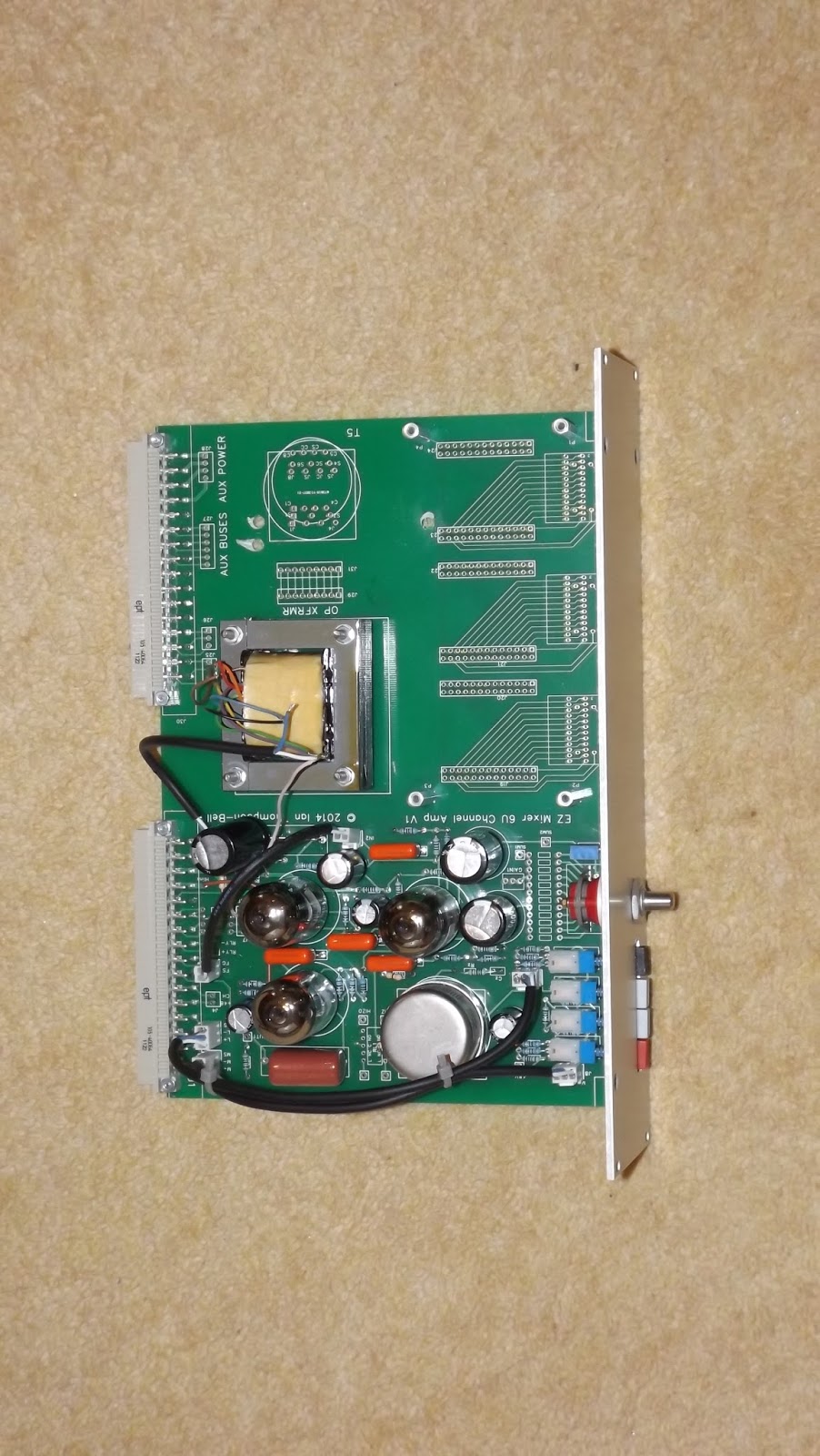
Here is a picture of the prototype 6U motherboard:


To the left is the mic pre and at the bottom right you can see the EQ switches and their associated IDC headers (two per switch). You can also see, above the switches, a space for fitting an output transformer. This means a module can be completely self contained with transformer balanced inputs and outputs. Unfortunately there are no spare pins on the standard 32 way EZTubeMixer connector for a balanced output so, rather than change the original 32 way pin out,  I have added a second 32 way connector. This will have the same basic pin out as the original but allocated differently. The mic and line balanced inputs can be used as inputs or as outputs. For example, you could have a balanced output from the mic pre which feeds an insert connected to the extra connector mic input pins. The balanced return would be fed to the extra connector balanced line input. You can see on the right hand side of the PCB where I have made provision for an extra input transformer for just this purpose. This would allow you to have a pre-EQ balanced insert or to use the mic pre and EQ independently.

After basic assembly, the PCB looks like this:


The uncommitted EQ switch and IDC headers idea is fine in theory but it did not work out in practice. The capacitance of the ribbon cable seriously upset the operation of the EQ, especially on the high frequency ranges and they also consume a lot of space on the EQ daughter-board. I wanted to retain the mother/daughter board flexibility, so I looked at simplifying the wiring between the two.

At that stage, the prototype 6U PCB had provision for three switches. Each one is tracked for two banks and up to 2 poles per back. Each bank is tracked to its own 26way IDC connector which means there is a total of six connectors.

The first EQ I worked on was the Helios 69 EQ daughter board. As the bass switch uses 2 banks it needs a pair of 26 way connections. These connectors take up a lot of room on the PCB, more than the switch would have done. There are only 26 connections required (two lots of 12 plus two commons) so a single 26 way connector would be sufficient. The only reason to have two 26 way connectors is if a four pole 6 way switch is required.

I therefore decided to review the switches used in the current range of EQs to see if it would be possible to use just a single 26 way connector per switch. The table below shows the switches used in the current EQs.

EQ
LO
MID
HI
OTHER
3B PULTEC
2P6W
1P12W
1P6W

HELIOS 69
2P12W
1P12W
1P12W

REDD
2P12W
2P12W
1P12W
2P6W


It is clear that no more than two poles are required. In the 2P12W cases, the poles are on different banks but for the 2P6W case both poles are on the same bank. So, although we never need more than 2 poles, they can come from four possible places.

However, we never use both poles on the second bank, in fact we only ever use the first pole on the second bank when we use a 2P12W switch. This means we can forget the second pole in the second bank. Also, whatever switch we use, we always use the first pole on the first switch so this can be permanently tracked to the 26 way connector. Now all we are left with is selecting between the second pole on the first bank in the 2P6W. We can do this with a set of three pads and a link.

The 26 pins of the connector have been allocated as follows:


CONN PIN
SW PIN
CONN PIN
SW PIN
1
Bank 2 Pin1
2
Bank 1 Pin 1
3
Bank 2 Pin 2
4
Bank 1 Pin 2
5
Bank 2 Pin 3
6
Bank 1 Pin 3
7
Bank 2 Pin 4
8
Bank 1 Pin 4
9
Bank 2 Pin 5
10
Bank 1 Pin 5
11
Bank 2 Pin 6
12
Bank 1 Pin 6
13
Bank 2 Pin 7
14
Bank 1 Pin 7
15
Bank 2 Pin 8
16
Bank 1 Pin 8
17
Bank 2 Pin 9
18
Bank 1 Pin 9
19
Bank 2 Pin 10
20
Bank 1 Pin 10
21
Bank 2 Pin 11
22
Bank 1 Pin 11
23
Bank 2 Pin12
24
Bank 1 Pin 12
25
Bank 2 Com
26
Bank 1  Com


This scheme reduces the the number of connectors by half and would hopefully not affect the performance of the EQ. Here is a picture of the updated 6U PCB:


Des[ite all these efforts,  the EQ performance was still compromised. So this scheme has been abandoned. Instead, each EQ type will have its own unique channel PCB. This means more PCBs have to be designed but it does mean the EQ will work as advertised. The first of these PCBs looks like this:


The mic pre section is unchanged but the EQ section now includes an almost complete Helios 69 style EQ. The only parts not on the PCB are the two pots, the peak/trough switch and the EQ in/out switches.. These will be connected to a very simple daughter board via a ribbon cable.

In parallel with this I have been developing the twin line channel (TLC) PCBs. These are intended to form the basis of a  line in line out mixer with two AUX sends and a pan pot per channel with two channels to a module Again a mother board daughter board concept is used but there are far fewer connections between mother and daughter board then in the case of the standard channel module.The first of these developed was the REDD EQ. The reason is that these EQ sections can be cut and pasted between Channel and TLC mother boards so I only have to lay out each EQ once. Here is a picture of the prototype REDD EQ TLC:


The top of the PCB is essentially a standard Twin Line Amp (TLA). At the top left of the PCB are three pots; these are the two AUX sends and the pan pot. Below them is the channel mute switch. Below the mute switch are two preset pots that are used to set  the gain of each half of the TLA so it can make up the loss in the EQ. These are arranged so as to be accessible through small holes in the front panel to simplify set up.

Below these is the EQ itself. It is a new version of the REDD EQ with all for switches in line. The top one is the 10KHz shelving EQ, the two middle ones are the mid boost/cut and mid frequency select switches and the bottom one is the 100Hz shelving EQ. The only component not on the PCB is the EQ in/out switch. If required this can be fitted directly to the front panel and wired to pads provided. It can be fitted in between the 10KHz switch and the gain trim pots.

Above and below the EQ are four holes labelled P1, P2, P3 and P4. These are for the pillars on which will be mounted the second identical EQ.  SImilarly, there are two holes above and below the AUX and pan pots on which will be mounted the AUX send, pan pot and channel mute controls of the second channel. The daughter EQ connects to the second input transformer and the second gain make up amp of the TLA section

The EQ has already been commissioned and it works well. The next stage is to check out the AUX send and pan pots then develop the two mother board PCBs.

Friday, 19 December 2014

6U Modules Part 1


The MKIII uses 6U high channel modules built using extruded aluminium 'cassettes' made by Fischer Electronik. First we need to sort out all the basic mechanical details of the cassettes and the key dimensions for determining the position of controls on the front panel. Later sections cover specific modules.

In general there are two distinct types of channel modules. First there is the regular channel amp based on the EZTubeMixer channel amplifier with its four push buttons and stepped gain control. Each one has an EQ section and an optional routing section. The second type is the twin line input channel. These have no mic pre controls but contain two identical line input channels each with a three band EQ and an optional routing section.

Basics

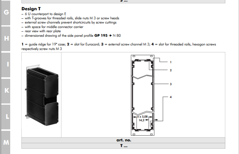
The Mark III 6U modules are based on an extruded aluminium cassette made by Fischer Elektronik in Germany. They have several types of 6U cassette but we need one that has a cut-out at the rear so it can be used with 3U backplane PCBs that have a centre support. The preferred type is therefore the Fischer model T:

Fischer6UTmodulebrochure.png

Note: this drawing shows that the top surface of the PCB is 14.2 mm from the left hand side of the front panel. This sets the position of all the controls mounted on the main 6U PCB and is crucial in calculating the x-position of holes on the front panel.

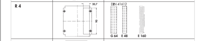
There are several rear panel options. Mostly we just need the type with a single connector hole at the top:

FischerR4rearpanel.png


All the modules are 14HP (2.8 inches wide). I have obtained a drawing of the Fischer standard dimensions for this size of front panel:


Fischer6U14HPfrontpaneldwg.png


The overall panel width is 70.9mm. The overall panel height is 261.8mm. The front panel fixing holes are 3.4mm diameter, countersunk and are set in 5mm from the edges.

A standard 6U PCB is 233.4mm tall. We assume the PCB is centred on the front panel. This means the bottom of the PCB is 14.2mm from the bottom of the front panel. This is crucial for calculating the y-position of holes on the front panel.

Mic Pre Channel Amplifier

The MK III mic pre channel amplifier is based on a standard 6U motherboard. This houses standard EZTubeMixer mic pre and gain make up amplifiers with the usual push buttons for phantom power, 20dB pad, mic/line selection and phase change and the standard 12 way Grayhill switch for gain setting. The Grayhill datasheet shows that the centre of the shaft of this switch is 9.35mm above the PCB surface and since the PCB surface s 14.2mm from the left hand side of the front panel, the switch shaft is:

14.2 + 9.35 = 23.55mm from the left hand edge of the front panel

The datasheet for the push buttons shows that the centre of their shafts is 5mm above the PCB surface or 19.2mm from the left hand edge of the front panel. The push buttons will take 6mm diameter round push on knobs so the hole diameter for these should be 6.5mm. The table below shows the y-coordinate of the push buttons and the gain switch on the PCB in mil, the equivalent y-coordinate of the holes for them on the front panel in mm and the corresponding x-coordinate in mm.


Control
PCB y-coord ( mil)
Panel y-coord (mm)
Panel x-coord (mm)
Phantom
8401
227.59
19.2
Pad
8007
217.59
19.2
Mic/Line
7614
207.59
19.2
Phase
7220
197.59
19.2
Gain
6433
177.6
23.55

In addition, provision is made for up to three two deck 12 way Grayhill switches for EQ use. Each switch is wired directly to a 26 way IDC connector. The centres of the shafts of the three switches are set at exactly 1.0, 2.6 and 4.2 inches respectively from the bottom of the PCB. In other words they are 1.6 inches apart starting 1 inch from the bottom of the PCB.. Since the bottom of the PCB is 14.2mm from the bottom of the front panel we can calculate the front panel positions of each switch:


Switch
x - position mm
y -position mm
1
23.55
39.6
2
23.55
80.24
3
23.55
120.88

Depending on the shaft size of the switches, the front panel hole diameter needs to be either  0.25 inches (6.35mm) for the one eighth inch diameter shaft and 0.375 inches (9.6mm) for the one quarter inch diameter shaft.

The EQ itself is housed on a daughter board mounted above the motherboard on pillars and connected to the EQ switches using ribbon cables. Ideally we would like the controls on this PCB to be the same distance from the right hand side of the front panel as the motherboard switches are from the left hand side i.e.

70.9 -23.55 = 47.35mm from the left hand side

Most of the controls on the daughter board will be EQ pots and my preferred type is made by OMEG. The shafts of these pots are 12.5mm from the surface of the PCB. Since the PCB is 1.6mm thick, to get the pot shafts in the right position the pillars need to be:

47.35 -12.5 -1.6 -14.2 = 19.05mm tall.

This is just enough to clear the switches but makes no allowance for the legs of components on the daughter board. In addition 19mm pillars are non-standard so I have decided to use 20mm pillars. This means the EQ pots are 1mm closer to the right hand side of the front panel. This means the x-position of the pot shafts on the front panel is:

14.2 + 20 +1.6 + 12.5 = 48.3mm

The daughter boards is supported by four pillars. The bottom pair are 0.252 inches from the bottom of the PCB. The motherboard fits into slots in the enclosure extrusions so the daughter PCB has to be a little smaller so as not to foul the enclosure. So, the bottom pillars on the daughter board are 0.160 inches from the bottom. If we want the the EQ pots on the daughter board to line up with the EQ switches on the motherboard then the pots need to be:

0.252 - 0.160 = 0.092 inches lower down the PCB

so the PCB y- positions of the pots are:  0.908, 2.508 and 4.108 inches respectively.

There is room between these pots for additional controls where required. To summarise, the front panel positions of the pots are:


Pot
x - position mm
y -position mm
1
48.3
39.6
2
48.3
80.24
3
48.3
120.88

Lastly, there is a pre-set potentiometer used to set the EQ gain make up that needs to be accessible through a small hole in the front panel. The screw of the pot is 7.9mm above the PCB so its x-coordinate is 14.2 + 7.9 = 22.1mm.  The centre of the pads of the pot is 5777 mil from the bottom of the PCB. However, the screw is 50 mil below this so the screw is 5727 mil from the bottom of the PCB. Its front panel y-coordinate is therefore:

5.272 * 25.4 + 14.2 = 148.11mm

The hole size needs to be large enough to accommodate a small screwdriver about 3.2mm in diameter so we will make this hole 4mm diameter.

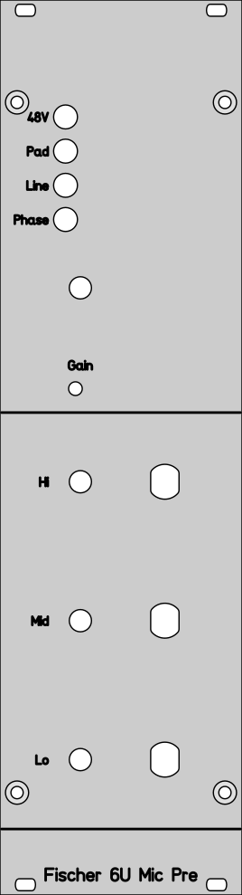
The front panel layout below shows the the basic layout of the controls discussed above:

6UFischermicprereference.png


Specific EQs will be described in subsequent posts.