V2, the output stage, is configured as a mu follower using a 6922 tube. For better drive capability at the expense of higher distortion, it can be configured as an SRPP stage.
V1, the input stage, is also configured as a mu follower but with a few extras. The key additions are R6 and R18. R6 allows the cathode of V1B to be raised high enough that R18 can provide NFB right down to dc, just as in the Eurochannel, to ensure stability at all gain settings. The closed loop gain is set by R19.
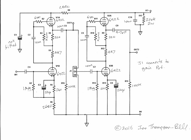
I have not built this configured with NFB but I have simulated it and it does perform well. The first one I built was a straight pair of mu follower stages. Here is the schematic for this with component values added:
As you can see, the NFB network is not used. The 220 ohm cathode resistors bias the mu followers at about 12mA each which is necessary for them to be able to drive a 600 ohm load via a 2:1 step down transformer. The first stage could be biased at a lower current because it usually only has to drive a 10K gain pot. Here is a pic of the PCB:
The PCB has all the usual EZTubeMixer fixtures and fittings including the 32 way DIN connector, mic and line inputs, phantom power, external fader connection, buses and provision for fitting an input transformer. Notice the two tubes are at the top so their heat does not flow past any passive components. This is not always the case in the Eurochannel and Twin Line Amp PCBs. It is made easier of course by having only two tubes. I am still not certain that three tubes could be squeezed into this size PCB but I am pretty certain they would fit in a 6U version, but that is something for later.
In the centre you can see the tracking for the pair of 9 way right angled headers that connect the tube mounting PCB to this PCB. And that is the reason this is the V2 PCB. In the first version I managed to get this connector mirror imaged! At least the boards could be used for mechanical mock ups. Talking of mechanics, you will notice there is quite a bit of bare PCB on the left which will be behind the front panel. This is to leave sufficient space for the new front panel mounted controls PCBs which give maximum flexibility in positioning front panels controls. Also, the 100uF 250V capacitor used to couple the gain setting resistor is too tall to be mounted normally so it has to be laid on its side. I could find only one source of a 100uF 250V electrolytic capacitor so I decided to stick with radial leaded types.
In performance terms it seems to be virtually identical to the original 14HP wide version. However, I do need to operate this version ,without the bottom screen, side by side with the 14HP Fischer module version, to measure exactly how good the new mechanicl system screens the electronics.


No comments:
Post a Comment